background image

Technical data

145

Technical data 

What this chapter contains

This chapter contains the technical specifications of the drive eg, ratings, frame 
sizes and technical requirements, provisions for fulfilling the requirements for CE 
and other markings, and warranty information.

Ratings

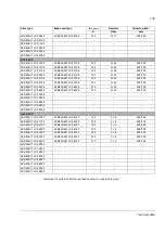
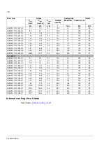
The rating for the drive with a 50 Hz supply are given below. The symbols are 
defined below the table.

Drive type

Nominal ratings

No-overload 

use

Light-overload use

Heavy-duty use

I

cont.max

I

max

P

contmax

I

2N

P

N

I

2hd

P

hd

A (AC)

A

kW

A

kW

A

kW

U

= 400 V

ACS800-17LC-0110-3

159

251

90

153

90

119

55

ACS800-17LC-0140-3

205

251

110

197

110

153

75

ACS800-17LC-0170-3

240

335

132

230

132

180

90

ACS800-17LC-0200-3

295

437

160

283

160

221

132

ACS800-17LC-0260-3

377

512

200

362

200

282

160

ACS800-17LC-0350-3

500

674

250

480

250

374

200

ACS800-17LC-0430-3

625

837

355

600

355

468

250

ACS800-17LC-0580-3

835

1037

500

802

450

625

355

ACS800-17LC-0870-3

1250

1590

710

1200

710

935

500

ACS800-17LC-1130-3

1635

1994

900

1570

900

1223

710

ACS800-17LC-1680-3

2430

2941

1400

2333

1400

1818

1000

ACS800-17LC-2220-3

3210

3906

1800

3082

1800

2401

1400

ACS800-17LC-3300-3

4765

5799

2800

4574

2400

3564

2000

U

= 500 V

ACS800-17LC-0120-5

139

232

90

133

75

104

55

ACS800-17LC-0170-5

191

252

132

183

110

143

90

ACS800-17LC-0210-5

238

335

160

228

160

178

110

ACS800-17LC-0250-5

290

430

200

278

160

217

132

ACS800-17LC-0310-5

355

515

200

341

200

266

160

ACS800-17LC-0410-5

475

673

315

456

315

355

200

ACS800-17LC-0520-5

595

838

400

571

400

445

315

ACS800-17LC-0690-5

795

1042

560

763

500

595

400

ACS800-17LC-1030-5

1190

1589

800

1142

800

890

630

ACS800-17LC-1350-5

1560

1996

1000

1498

1000

1167

800

ACS800-17LC-2000-5

2310

2943

1600

2218

1600

1728

1200

ACS800-17LC-2640-5

3050

3885

2000

2928

2000

2281

1600

ACS800-17LC-3930-5

4540

5801

3200

4358

3200

3396

2800

Summary of Contents for ACS800-17LC

Page 1: ...ABB industrial drives Hardware manual ACS800 17LC Drives 55 to 5200 kW ...

Page 2: ...C Hardware Manual 3AUA0000065339 ACS800 IGBT Supply Control Program Firmware Manual 3AFE68315735 ACS800 Standard Control Program Firmware Manual 3AFE64527592 Option manuals and guides ACS800 1007LC Liquid Cooling Unit User s Manual 3AFE68621101 ACS800 607LC 3 phase Brake Units Hardware Manual 3AFE68835861 ACS800 Brake Control Program Firmware Manual 3AFE68835631 ACW 621 Braking Chopper Sections Us...

Page 3: ...ACS800 17LC Drives 55 to 5200 kW Hardware Manual 3AUA0000065339 REV B EN EFFECTIVE 2016 06 07 2016 ABB Oy All Rights Reserved ...

Page 4: ......

Page 5: ...AFE68843758 B Swedish SV 3AFE68822092 B English EN 3AFE68912148 B German DE 3AFE68912156 B Finnish FI 3AFE68912164 B Italian IT 3AFE68912172 B Swedish SV 3AFE68715491 C English EN 3AFE68987784 C German DE 3AFE68987792 C Finnish FI 3AFE68987806 C Italian IT 3AFE68987814 C Swedish SV 3AFE68835861 D English EN 3AUA0000040346 D German DE 3AUA0000040370 D Finnish FI 3AUA0000040368 D Italian IT 3AFE6862...

Page 6: ...l and corrosion inhibitor Cortec VpCl 649 in new Antifrogen L tested units and drives is wanted system must be flushed before as Antifrogen L remains in the system after testing Flushing procedure described in the document Usage of Antifrogen L in ACS800LC Drives 3AXD10000511935 must be followed If new units or drives tested with Antifrogen L are connected to old ACS800 industrial liquid cooled un...

Page 7: ...usable in storage temperatures down to 40 C 40 F Note that operation below 0 C 32 F is not allowed regardless of the freezing point of the coolant WARNING The warranty does not cover damage occurring from use of improper coolant Temperature limits Ambient temperature See the technical data of the drive unit Freeze protection The freezing point of the coolant is determined by the concentration of h...

Page 8: ...nlet temperature for ACS800 liquid cooled drive Drive with the optional cooling unit ACS800 1007LC 38 C when the drive output capacity is not derated 38 C 45 C when the drive output capacity is derated by 1 per 1 C temperature increase Drive without the optional liquid cooling unit ACS800 1007LC 42 C when the drive output capacity is not derated 42 C 48 C when the drive output capacity is not dera...

Page 9: ...ith the atmospheric pressure when the cooling circuit is filled with coolant Air counterpressure in the expansion tank 40 kPa Design pressure Ps 600 kPa Nominal pressure difference between main in out lines 120 kPa with 25 75 volume coolant solution 150 kPa with 50 50 coolant solution Maximum pressure difference between main in out lines 200 kPa ...

Page 10: ...Update notice 6 ...

Page 11: ...cability 21 Target audience 21 Contents 21 Related documents 22 Categorization by frame size and option code 22 Quick installation and start up flowchart 22 Terms and abbreviations 23 Hardware description What this chapter contains 27 Product overview 27 Single line circuit diagram of the drive 28 Example circuit diagram frames R7i R7i and R8i R8i 28 Example circuit diagram frame 2 R8i 2 R8i 29 Bl...

Page 12: ...Control of the inverter unit and motor 47 Control panel 47 Connections and use of the I O in the inverter unit 47 Circuit boards 47 Type designation labels 48 Drive label 48 Supply inverter and brake module label 48 Type designation key 50 Type code of the basic configuration 50 Option codes 50 Mechanical installation What this chapter contains 55 Checking the installation site 55 Required tools 5...

Page 13: ...Selecting the control cables 79 General rules 79 Relay cable 80 Control panel cable 80 Coaxial cable for use with Advant Controllers AC 80 AC 800 80 Routing the cables 80 Separate control cable ducts 81 Protecting the drive input power cable motor and motor cable in short circuit situation and against thermal overload 81 Protecting the drive and input power cable in short circuit situations 81 Pro...

Page 14: ...n H359 94 Connection diagram single inverter module feeds one motor 94 Connection diagram parallel inverter modules feed one motor 95 Connection procedure 96 Connecting the motor cable units with the common motor cable connection terminals cubicle option H359 98 Connection diagram 98 Connection procedure 98 Connecting external power supply for the auxiliary circuits 100 Frames R7i R7i and R8i R8i ...

Page 15: ... in the application program 117 Terms and abbreviations 117 Actual signals and parameters of supply unit in inverter unit program 117 Fault tracing LEDs 119 Warning and fault messages 119 Warning Fault message from the unit not being monitored by the control panel 119 Conflicting ID numbers 119 Maintenance What this chapter contains 121 Maintenance intervals 121 Fans 121 Replacing the cooling fan ...

Page 16: ...ng inhibitor 140 Specifications 141 Temperature limits 141 Pressure limits 141 Water quality 142 Freeze protection and corrosion inhibition 142 Glycol concentration 142 Materials 143 Technical data What this chapter contains 145 Ratings 145 Definitions 146 Derating 146 Temperature derating 146 Altitude derating 147 Type equivalence table 147 1 phase brake choppers option D150 and resistors option ...

Page 17: ...protection 162 Auxiliary circuit current consumption 164 Applicable standards 165 CE marking 166 Compliance with the European Low Voltage Directive 166 Compliance with the European EMC Directive 166 Compliance with the European Machinery Directive 166 Compliance with EN 61800 3 2004 166 Definitions 166 Category C2 167 Category C3 167 Category C4 168 UL marking 169 UL checklist 169 CSA marking 169 ...

Page 18: ...Table of contents 12 ...

Page 19: ...gs caution you about conditions which can result in serious injury or death and or damage to the equipment and advise on how to avoid the danger The following warning symbols are used in this manual Electricity warning warns of hazards from electricity which can cause physical injury and or damage to the equipment General warning warns about conditions other than those caused by electricity which ...

Page 20: ...rcuits may cause dangerous voltages inside the drive even when the main power on the drive is switched off Do not make any insulation or voltage withstand tests on the drive or drive modules When reconnecting the motor cable always check that the phase order is correct When joining shipping splits if any check the cable connections at the joints before switching on the supply voltage Live parts on...

Page 21: ...rounding conductors are adequately sized as required by safety regulations In a multiple drive installation connect each drive separately to protective earth PE Do not install a drive equipped with optional EMC filter E202 to an ungrounded power system or a high resistance grounded over 30 ohms power system Note Power cable shields are suitable for equipment grounding conductors only when adequate...

Page 22: ...ve Stop the motor Ensure that there is no voltage on the drive power terminals according to step 1 or 2 or if possible according to the both steps 1 Disconnect the motor from the drive with a safety switch or by other means Measure that there is no voltage present on the drive input or output terminals L1 L2 L3 U1 V1 W1 U2 V2 W2 R R 2 Ensure that the motor cannot rotate during work Make sure that ...

Page 23: ...cal supply Recommendation Do not fasten the cabinet by riveting or welding However if electric welding is the only way to mount the cabinet follow the instructions given in chapter Mechanical installation Ensure that welding fumes are not inhaled If the welding return wire is connected improperly the welding circuit may damage electronic circuits in the cabinet Printed circuit boards Fiber optic c...

Page 24: ...liquid Do not work on the liquid cooling system until the pressure is lowered down by stopping the pumps High pressure warm coolant 6 bar max 50 C is present in the internal cooling circuit when it is in operation Before power switch on make sure that the internal cooling circuit is filled up with coolant Running the pump dry will damage it Also the drive will not cool down Units with a liquid coo...

Page 25: ...anel keys and or commands via the I O board of the drive The maximum allowed number of charging cycles of the DC capacitors ie power ups by applying power is five in ten minutes Do not use the Prevention of unexpected start function or Safe torque off function for stopping the drive when the inverter unit s is running Give a Stop command instead Note If an external source for start command is sele...

Page 26: ...Safety instructions 20 ...

Page 27: ...s and electrical schematic symbols The manual is written for readers worldwide Both SI and imperial units are shown Contents The chapters of this manual are briefly described below Safety instructions gives safety instructions for the installation commissioning operation and maintenance of the drive Introduction to the manual introduces the manual Hardware description describes the operation princ...

Page 28: ...ions are listed in section Type designation key on page 50 Quick installation and start up flowchart Task See Plan the installation Check the ambient conditions ratings required external cooling arrangements input power connection compatibility of the motor motor connection and other technical data Select the cables Technical data page 145 Planning the electrical installation page 69 Option manual...

Page 29: ...necting parallel connected supply and inverter modules to the RDCU ASTO Safe torque off board An optional board used to implement the Safe torque off function Brake chopper Conducts the surplus energy from the intermediate circuit of the drive to the brake resistor when necessary The chopper operates when the DC link voltage exceeds certain maximum limit The voltage rise is typically caused by dec...

Page 30: ...enclosed inside a metal enclosure Used as the supply module in regenerative and low harmonic drives IGBT supply unit ISU IGBT supply modules under control of one control board and related components See IGBT supply module Inverter Converts direct current and voltage to alternating current and voltage Inverter module Inverter bridge related components and drive DC link capacitors enclosed inside a ...

Page 31: ...the use of which is determined by the control program loaded onto the board The RMIO is widely used in the ACS800 product series eg for controlling drive modules inverter units supply units cooling units brake units etc See also RDCU STO Safe torque off function THD Total harmonic distortion Term Abbreviation Explanation ...

Page 32: ...Introduction to the manual 26 ...

Page 33: ... describes the operation principle and the construction of the drive in short Product overview The ACS800 17LC is a four quadrant cabinet installed liquid cooled drive for controlling asynchronous AC induction motors and generators and permanent magnet synchronous motors and generators ...

Page 34: ... R8i drives without any EMC du dt filter or brake options The supply unit and inverter unit have their own control boards RDCU control units and control programs M Ground fault monitoring Q954 230 V AC or 115 V AC G304 DC bus M 3 230 115 V AC M 230 115 V AC Charging circuit Supply unit Inverter unit Main contactor LCL filter Main switch disconnector Main supply ...

Page 35: ... and the inverter unit consist of two parallel frame R8i converter modules The supply unit and inverter unit have their own control boards RDCU control units and control programs M Ground fault monitoring Q954 230 V AC or 115 V AC G304 M DC bus M 3 230 115 V AC 230 115 V AC Main supply M M 230 115 V AC 230 115 V AC Charging circuit Supply unit Inverter unit Main breaker LCL filter ...

Page 36: ... R8i are equipped with a main switch disconnector and contactor Drives of frame sizes n R8i n R8i are equipped with an air circuit breaker 2 Optional EMC filter E202 3 LCL filter 4 Supply module 5 Brake chopper option D150 6 Brake resistors option D151 7 3 phase brake chopper option D152 8 Inverter module The module is equipped with du dt as standard For frame R7i the filter is optional E205 9 Sin...

Page 37: ... 9 inverter modules forming the inverter unit and optional equipment The actual arrangement of the cubicles varies from type to type and the selected options An example line up is shown below ACS800 17LC 1240 7 C141 D152 A Auxiliary control cubicle optional B Incoming cubicle C LCL filter cubicle D Supply module cubicle E Inverter module cubicle F Brake chopper cubicle option D152 G Liquid cooling...

Page 38: ... connection terminals 8 Main switch 9 Input fuses 10 Cabinet fan 11 LCL filter 12 IGBT supply module behind the swing out frame 13 Inverter module behind the swing out frame 14 Swing out frame with supply and inverter unit control electronics I O terminal blocks and communication options See Swing out frame layout on page 33 15 Cooling fans 16 Motor cable connection terminals busbars behind the fa...

Page 39: ... Supply control unit RDCU including the control board RMIO 4 I O module adapter AIMA optional 5 24 V DC power supply 6 24 V DC back up accumulator auxiliary power interface board RAPI 7 Relay for disconnecting the power supply for the cooling fans and connecting the heating on when the drive is powered but not running 8 Pt100 relays for motor temperature supervision option L506 9 Internal control ...

Page 40: ...s such as auxiliary voltage transformer require an auxiliary control cubicle A 600 mm wide cubicle is shown below No Description 1 Handle of main switch for auxiliary circuits 2 Main switch for auxiliary circuits 3 Space for control relays devices etc 4 Air to liquid heat exchanger 5 Cooling fan 6 Auxiliary voltage transformer T10 Door closed Door open 6 3 4 5 2 1 ...

Page 41: ... Start 2 Emergency stop reset push button option G331 3 Handle of grounding switch option F259 4 Meters options G335 3G335 G334 5 Main switch disconnector air circuit breaker 6 Charging circuit switch and handle 7 Busbars for input power cables 8 PE main busbar of the cabinet behind the cooling liquid pipe 9 Heat exchanger and fans 10 Grounding switch option F259 4 6 5 9 10 8 7 3 1 2 Doors closed ...

Page 42: ...s of frame 2 R8i is shown below The larger units employ similar cubicles in parallel No Description A LCL filter cubicle B Supply module cubicle 1 AC fuses 2 LCL filter components 2 L 1 C 3 DC fuses 4 Supply modules behind the swing out frame 5 Swing out frame for the supply unit control electronics 6 Fans Doors closed Doors open 1 4 6 3 2 5 A B ...

Page 43: ...g out frame aside Depending on selected options the actual equipment may differ from what is depicted below No Description 1 Auxiliary voltage distribution terminal block 2 24 V DC power supply 3 24 V DC back up accumulator auxiliary power interface board RAPI 4 Supply module control unit RDCU including the control board RMIO 5 Circuit breakers for auxiliary circuits 6 Ground fault monitoring rela...

Page 44: ...nd the swing out frame 6 Swing out frame with inverter unit control electronics I O terminal blocks and communication options 7 Motor cable terminals busbies behind the fans 8 Terminal block for connection of prevention of unexpected start circuit option Q950 9 Terminal block for connection of motor temperature supervision option L505 or L506 10 Fan 11 Motor grounding terminal common cabinet groun...

Page 45: ...es behind the swing out frame 6 Swing out frame with inverter unit control electronics I O terminal blocks and communication options 7 Motor cable terminals busbies behind the fans 8 Terminal block for connection of prevention of unexpected start circuit option Q950 9 Motor grounding terminal common cabinet grounding busby behind the coolant pipe 10 Fans 11 Terminal block for connection of motor t...

Page 46: ...ng the swing out frame aside Depending on selected options the actual equipment may differ from what is depicted below No Description 1 Inverter control unit RDCU including the control board RMIO 2 RDCO DDCS Adapter Module options L508 and L509 3 APBU Branching Unit with parallel connected inverter modules 4 24 V DC power supply 5 24 V DC back up accumulator Auxiliary Power Interface Board RAPI 6 ...

Page 47: ...n optical branching unit In the inverter modules the optic link connects to the AINT board the terminals of which are accessible through a hole on the front panel of the module 1 AC busbars knives U2 V2 W2 Fit into quick connector on the rear assembly plate of the cabinet 2 DC busbars 3 Fiber optic connectors V1 V2 control board RMIO connection Other fiber optic connectors are not in use in supply...

Page 48: ...te By default the control panel of the drive is set to control the inverter unit Control board RMIO Control unit RDCU Optional module 1 I O extension RAIO RDIO pulse encoder interface RTAC or fieldbus adapter RMBA RDNA RPBA etc Optional module 2 I O extension RAIO RDIO or pulse encoder interface RTAC Optional module 3 DDCS communication option RDCO 01 RDCO 02 or RDCO 03 fiber optic link RDCO CH0 R...

Page 49: ...witches the main and auxiliary voltages to the drive on and off Supply transformer disconnecting push button Q959 The red push button disconnects the control voltage from the supply transformer breaker The push button is added on the cabinet door at the factory by ABB The installer of the drive must wire the button to the breaker control circuit on the installation site Operating switch Auxiliary ...

Page 50: ...d Emergency stop push button An emergency stop button is included with options Q951 and Q952 Reset button A reset button is included with options Q951 and Q952 The button resets an emergency stop after which the supply unit can be started using the operating switch Note Drive faults are reset via the drive control panel or serial communication G E M ER EN C Y O ST P RESET ...

Page 51: ...rol circuitry DI3 ACK MAIN CONTACTOR Main breaker contactor supervision 1 closed enables supply unit start Contact in main breaker contactor control circuit DI4 EARTH FAULT Ground fault supervision Can be activated or inactivated by parameter 1 No fault Not in use as default Insulation monitoring device option Q954 DI5 ALARM FAULT Supervision of cooling unit Can be activated or inactivated by para...

Page 52: ...24 V DC 250 mA 2 GND X25 1 RO1 Charging contactor control open 0 close 1 2 RO1 3 RO1 X26 1 RO2 LCU control off 0 on 1 2 RO2 3 RO2 X27 1 RO3 Main breaker contactor control open 0 close 1 2 RO3 3 RO3 1 Not in use as default For details see the delivery specific circuit diagrams of the drive The diagrams show supply unit on off control main breaker supervision and on off control charging contactor on...

Page 53: ...l delivered with the drive The control panel is wired to the supply unit and inverter unit using a Y splitter Connections and use of the I O in the inverter unit See page 103 Circuit boards 1 The RDCU is equipped with an auxiliary power interface board RAPI when not equipped with terminals for connecting external control voltage option G307 The RAPI ensures that the POWER FAIL function of the RMIO...

Page 54: ...cturing year and week respectively The remaining digits complete the serial number so that there are no two units with the same serial number The type designation label is located on the front cover An example label is shown below Supply inverter and brake module label The type designation label of the converter module includes the ratings valid markings a type code and a serial number The module ...

Page 55: ...The next four digits refer to the unit s manufacturing year and week respectively The remaining digits complete the serial number so that there are no two units or modules with the same number 2 Type code See section Type designation key page 50 3 Valid markings 4 Ratings of converter module when in inverter use 5 Ratings of converter module when in supply module use 6 Ratings of converter module ...

Page 56: ...d cooled four quadrant drive 13 16 Size Refer to the rating tables page 145 18 Voltage rating 4 Voltage range 380 415 V AC 5 Voltage range 440 500 V AC 7 Voltage range 525 690 V AC Class Code Description Degree of protection B055 IP54 UL Type 12 Not available with C134 Construction C121 Marine construction reinforced mechanics and fastening marking of conductors according to G341 marine door handl...

Page 57: ...lue lighted on the cabinet door Meters G335 A meter in one phase 3G335 A meter in three phases G334 V meter with selector switch Wire markings G338 Equipment pin numbers are printed on wires between modules and on wires connected to equipment G339 Equipment and terminal block pin numbers are printed on wires between modules and on wires connected to equipment and terminal blocks Main circuit condu...

Page 58: ...dule Starter for auxiliary motor fan M600 to M605 and terminals for external voltage supply for liquid cooling unit s pump M600 Trip limit setting range 1 1 6 A M601 Trip limit setting range 1 6 2 5 A M602 Trip limit setting range 2 5 4 A M603 Trip limit setting range 4 6 3 A M604 Trip limit setting range 6 3 10 A M605 Trip limit setting range 10 16 A M633 Terminals for 380 415 V 50 Hz or 380 480 ...

Page 59: ...ain breaker contactor see also G331 Q952 Emergency stop of Category 1 with opening the main breaker contactor see also G331 Q954 Ground fault monitoring for IT ungrounded systems Q963 Emergency stop of Category 0 without opening the main breaker contactor see also G331 Q964 Emergency stop of Category 1 without opening the main breaker contactor see also G331 Q959 Supply transformer breaker disconn...

Page 60: ...Hardware description 54 ...

Page 61: ...ness must be checked with a spirit level before the installation of the cabinets into their final position The maximum allowed deviation from the surface level is 5 mm in every 3 metres The installation site should be levelled if necessary as the cabinet is not equipped with adjustable feet The wall behind the unit must be of non flammable material Note Wide cabinet line ups are delivered as shipp...

Page 62: ...ns of damage Before attempting installation and operation check the information on the type designation label of the drive to verify that the delivery is of the correct type See Type designation key on page 50 Moving the unit Moving the unit by crane Use the steel lifting bars attached to the top of the cabinet Insert the lifting ropes or slings into the holes of the lifting bars The lifting bars ...

Page 63: ...herefore careful when transporting the unit Avoid tilting the cabinets The units are to be moved only in the upright position If using a pallet truck check its load capacity before attempting to move the unit Remove the wooden bottom frame which is part of the shipment Lay the unit on the rollers and move it carefully until close to its final location Remove the rollers by lifting the unit with a ...

Page 64: ...Placing the unit The cabinet can be moved into its final position with an iron bar and a wooden piece at the bottom edge of the cabinet Care is to be taken to properly place the wooden piece so as not to damage the cabinet frame ...

Page 65: ...placement Note Any height adjustment must be done before fastening the units or shipping splits together Height adjustment can be done by using metal shims between the bottom frame and floor 2 Remove the lifting bars Use the original bolts to block any unused holes In marine units use the holes for fastening the cabinet from top 3 Slide Axilock connectors onto the liquid pipe ends One connector pe...

Page 66: ...ce between the clamps is 800 mm 31 5 If there is not enough working space behind the cabinet for mounting replace the lifting bars at the top with L brackets not included and fasten the top of the cabinet to the wall Clamp dimensions in millimetres Cabinet frame Distances between slots Cubicle Width mm Distance in millimetres and inches 300 150 5 9 400 250 9 85 500 350 13 78 600 450 17 72 700 550 ...

Page 67: ...e cabinet for mounting replace the lifting lugs at the top with L brackets not included and fasten the top of the cabinet to the wall Fastening holes inside the cabinet arrowed 25 mm 0 985 Distances between the bottom fastening holes Bolt size M10 to M12 3 8 to 1 2 Cubicle Width Distance between holes 300 150 mm 5 9 400 250 9 85 600 450 17 7 700 550 21 65 800 650 25 6 Outer Ø31 mm 1 22 Fastening t...

Page 68: ...ng M10 or M12 screws Note Welding is not recommended see page 67 2 If there is not enough room behind the cabinet for installation clamp the rear ends of the flat bars 3 Remove the lifting bars and fasten the top of the cabinet to the rear wall and or roof using brackets 1 2 3 Cabinet roof M16 bolt L bracket Back panel of cabinet Flat bars at base of cabinet Clamps not included in delivery ...

Page 69: ... are pushed together the pipe ends come too close to each other and the connectors cannot be installed any more Fastening the cabinets together Two shipping splits are joined in a joining cubicle Special M6 screws for fastening the shipping splits together are enclosed in a plastic bag inside the cabinet The threaded bushings are already mounted on the post Fasten the front post and the rear post ...

Page 70: ...ther 3 Centre the Axilock connector onto the pipe ends 4 Tighten the connector bolts to a torque shown on the label attached to the connector Connecting the PE busbars Connect the PE busbars as shown below Parallel misalignment max 3 mm 0 2 Angular error max 2 in any direction Axial gap 5 to 15 mm 0 2 to 0 6 2 3 Tightening torque 35 40 N m 25 30 lbf ft Strength class 8 8 Spring washer Plain washer...

Page 71: ...ngth class 8 8 4 Refit the covering plate WARNING Do not place the spring washer against the joint piece Use the plain washer with electroplated zinc coating and blue passivation instead An unpassivated zinc coated spring washer positioned directly against the joint piece would cause corrosion a Side views of busbar connection a joint piece b plain washer with electroplated zinc coating and blue c...

Page 72: ...ion at the back which the floor must carry Viewed from above Side view This area can be used for a cable duct Prevent the cooling air flow from the cable duct to the cabinet by bottom plates To ensure the degree of protection for the cabinet use the original bottom plates delivered with the unit With user defined cable entries take care of the degree of protection fire protection and EMC complianc...

Page 73: ...t Cabinets with flat bars at the base Weld only the flat bar under the cabinet never the cabinet frame itself Clamp the welding electrode onto the flat bar about to be welded or to the next flat bar within 0 5 metres of the welding point WARNING If the welding return wire is connected improperly the welding circuit may damage electronic circuits in the cabinet The thickness of the zinc coating of ...

Page 74: ...Mechanical installation 68 ...

Page 75: ... The drive is equipped with a main switch disconnector as standard Checking the compatibility of the motor and drive Use an AC induction motor or a permanent magnet synchronous motor with the drive Several induction motors can be connected at a time but only one permanent magnet motor Controlling a permanent magnet motor is only allowed using the ACS800 permanent magnet synchronous machine control...

Page 76: ...le at the motor terminals depending on the attenuation and reflection properties of the motor cable and the terminals This can cause additional stress on the motor and motor cable insulation Modern variable speed drives with their fast rising voltage pulses and high switching frequencies can generate current pulses that flow through the motor bearings which can gradually erode the bearing races an...

Page 77: ... insulation system ABB du dt filter insulated N end bearing and ABB common mode filter PN 100 kW and frame size IEC 315 100 kW PN 350 kW or frame size IEC 315 PN 350 kW or frame size IEC 400 PN 134 hp and frame size NEMA 500 134 hp PN 469 hp or frame size NEMA 500 PN 469 hp or frame size NEMA 580 A B B Random wound M2_ M3_ and M4_ UN 500 V Standard N N CMF 500 V UN 600 V Standard du dt du dt N du ...

Page 78: ...MF 500 V UN 600 V Reinforced ÛLL 1600 V du dt du dt N du dt N CMF or du dt CMF or Reinforced ÛLL 1800 V N or CMF N CMF 600 V UN 690 V Reinforced ÛLL 1800 V du dt du dt N du dt N CMF Reinforced ÛLL 2000 V 0 3 microsecond rise time N CMF N CMF Abbreviation Definition UN Nominal voltage of the supply network ÛLL Peak line to line voltage at motor terminals which the motor insulation must withstand PN...

Page 79: ...ly control program parameter settings select the motor insulation system according to the increased DC voltage level especially in the 500 V supply voltage range Calculating the rise time and the peak line to line voltage The peak line to line voltage at the motor terminals generated by the drive as well as the voltage rise time depend on the cable length The requirements for the motor insulation ...

Page 80: ...e must be rated according to permissible touch voltage appearing under fault conditions so that the fault point voltage will not rise excessively when a ground fault occurs 600 V AC cable is accepted for up to 500 V AC For 690 V AC rated equipment the rated voltage between the conductors of the cable should be minimum 1 kV Use symmetrical shielded motor cable see page 76 Ground the shield s of mot...

Page 81: ...ctromagnetic emission of the whole drive system as well as motor bearing currents and wear Note The cabinet configuration of the drive may require multiple supply and or motor cabling Refer to the connection diagrams in chapter Electrical installation Keep the motor cable and its PE pigtail twisted screen as short as possible in order to reduce high frequency electromagnetic emissions Cross sectio...

Page 82: ... 44 49 54 69 83 107 130 151 174 199 235 677 912 1110 1412 1665 1920 2257 2683 86 104 134 163 189 218 249 294 677 912 1110 1412 1665 1920 2257 2683 2 3 70 21 Cu 2 3 95 29 Cu 2 3 120 41 Cu 2 3 150 41 Cu 2 3 185 57 Cu 2 3 240 72 Cu 2 32 2 38 2 41 2 44 2 49 2 54 214 260 302 348 398 470 1110 1412 1665 1920 2257 2683 268 325 378 435 498 588 1110 1412 1665 1920 2257 2683 3 3 150 41 Cu 3 3 185 57 Cu 3 3 2...

Page 83: ...123 177 255 354 505 773 970 1268 1554 1954 2313 2724 3186 3904 2 3 70 35 2 3 95 50 2 3 120 70 2 3 150 70 2 3 185 95 2 3 240 120 2 32 2 38 2 41 2 44 2 50 2 55 274 334 386 446 510 602 1554 1954 2313 2724 3186 3904 343 418 483 558 638 753 1554 1954 2313 2724 3186 3904 3 3 120 70 3 3 150 70 3 3 185 95 3 3 240 120 3 41 3 44 3 50 3 55 579 669 765 903 2313 2724 3186 3904 724 836 956 1129 2313 2724 3186 3...

Page 84: ...n open helix of copper tape The better and tighter the shield the lower the emission level and the bearing currents Recommended Symmetrical shielded cable three phase conductors and a concentric or otherwise symmetrically constructed PE conductor and a shield PE conductor and shield Shield Shield A separate PE conductor is required if the conductivity of the cable shield is 50 of the conductivity ...

Page 85: ...d type MC continuous corrugated aluminum armor cable or shielded cable is not required A dedicated ground cable is always required Note Do not run motor wiring from more than one drive in the same conduit Armored cable shielded power cable 6 conductor 3 phases and 3 ground type MC continuous corrugated aluminum armor cable with symmetrical grounds is available from the following suppliers trade na...

Page 86: ...ontrol panel option kits Coaxial cable for use with Advant Controllers AC 80 AC 800 75 ohm RG59 diameter 7 mm or RG11 diameter 11 mm Maximum cable length 300 m 1000 ft Routing the cables Route the motor cable away from other cable routes Motor cables of several drives can be run in parallel installed next to each other It is recommended that the motor cable input power cable and control cables be ...

Page 87: ...input cable with fuses In networks with a short circuit withstand of 65 kA or less standard gG fuses can be used No fuses need be installed at the drive input 90 min 500 mm 20 in Motor cable Input power cable Control cables min 200 mm 8 in min 300 mm 12 in Motor cable Power cable Drive 24 V 24 V 230 V Lead 24 V and 230 V 120 V control cables in separate ducts inside the cabinet Not allowed unless ...

Page 88: ...and motor cables against thermal overload when the cables are dimensioned according to the nominal current of the drive No additional thermal protection devices are needed WARNING If the drive is connected to multiple motors a separate thermal overload switch or a circuit breaker must be used for protecting each cable and motor These devices may require a separate fuse to cut off the short circuit...

Page 89: ...t are equipped with an internal ground fault protective function to protect the drive against ground faults in the drive motor and motor cable This is not a personnel safety or a fire protection feature Both ground fault protective functions can be disabled refer to the IGBT Supply Control Program Firmware Manual 3AFE68315735 English and the firmware manual of the drive control program respectivel...

Page 90: ...med without switching off the power supply to the drive The operator activates the prevention of unexpected start function using a switch mounted on a control desk When the function is activated the switch is opened and an indicator lamp will light WARNING The prevention of unexpected start function does not disconnect the voltage of the main and auxiliary circuits from the drive Therefore mainten...

Page 91: ...the drive by using the Safe torque off function If a running drive is stopped by using the Safe torque off function the drive will stop by coasting If this causes danger or is not acceptable the drive and machinery must be stopped using the appropriate stopping mode before using the Safe torque off function Note concerning permanent magnet motor drives in case of a multiple IGBT power semiconducto...

Page 92: ...tion Auxiliary circuit current consumption on page 164 Using power factor compensation capacitors with the drive Power factor compensation is not needed with AC drives However if a drive is to be connected in a system with compensation capacitors installed note the following restrictions WARNING Do not connect power factor compensation capacitors to the motor cables between the drive and the motor...

Page 93: ...1 Give a stop command to the drive 2 Wait until the drive decelerates the motor to zero speed 3 Open the contactor When you have selected to use DTC or vector motor control mode and motor coast stop or scalar control mode open the contactor as follows 1 Give a stop command to the drive 2 Open the contactor WARNING When the DTC or vector motor control mode is in use never open the output contactor ...

Page 94: ...o the unit Example bypass connection An example bypass connection is shown below Switching the motor power supply from drive to direct on line 1 Stop the drive and the motor with the drive control panel drive in local control mode or the external stop signal drive in remote control mode 2 Open the main contactor of the drive with S11 Description Q1 Drive main switch Q4 Bypass circuit breaker K1 Dr...

Page 95: ...ing the contacts of relay outputs Inductive loads such as relays contactors motors cause voltage transients when switched off The relay contacts of the RMIO board are protected with varistors 250 V against overvoltage peaks In spite of this it is highly recommended to equip inductive loads with noise attenuating circuits varistors RC filters AC or diodes DC in order to minimize the EMC emission at...

Page 96: ...e 2000 metres 6562 feet WARNING Wear appropriate protection when installing operating or servicing the RMIO board wiring and optional modules attached to the board The Protective Extra Low Voltage PELV requirements stated in EN 61800 5 1 are not fulfilled at altitudes above 2000 m 6562 ft ...

Page 97: ...drive Every drive has been tested for insulation between the main circuit and the chassis at the factory Also there are voltage limiting circuits inside the drive which cut down the testing voltage automatically Supply cable Check the insulation of the supply input cable according to local regulations before connecting to the drive Motor and motor cable Check the insulation of the motor and motor ...

Page 98: ...using a measuring voltage of 1 kV DC The insulation resistance must be higher than 1 Mohm Checking the compatibility with IT ungrounded and corner grounded TN systems EMC filter E202 is not suitable for use in an IT ungrounded system If the drive is equipped with EMC filter E202 disconnect the filter before connecting the drive to the supply network For detailed instructions on how to do this plea...

Page 99: ...uxiliary voltage transformer T10 is selected correctly according to the supply voltage 1 Open the door of the cabinet 2 Remove any shrouds that protect the input busbars and cable entries 3 Lead the cables into the inside of the cubicle It is recommended to apply 360 grounding of the cable shields at the entry as shown below PE L1 L2 L3 1 Incoming cubicle Notes 1 Input power connection L1 L2 L3 an...

Page 100: ...bar Connect the phase conductors to the input power terminals L1 L2 L3 For the tightening torques see page 155 5 Provide support for the cables whenever necessary 6 Refit all shrouds removed earlier and close the door Connecting the motor cable units with no common motor terminals cubicle option H359 Connection diagram single inverter module feeds one motor U2 V2 W2 PE M 3 U1 W1 V1 PE Inverter mod...

Page 101: ...d one motor WARNING The cabling from all inverter modules to the motor must be physically identical considering cable type cross sectional area and length U2 V2 W2 PE U2 V2 W2 M 3 U1 W1 V1 PE Inverter module cubicle PE Inverter module cubicle U2 V2 W2 U2 V2 W2 M 3 U1 W1 V1 PE ...

Page 102: ... interference and motor bearing current ground the cable shield 360 at the lead through 6 Connect the cables as follows Cut the cables to suitable length Strip the cables and conductors Fasten the cable lugs to the conductor ends Twist the cable shields into bundles and connect to cabinet ground busbar Connect the phase conductors to the output terminals See the appropriate connection diagram abov...

Page 103: ...rter module cubicle from front shroud removed 2 3 5 6 4 4 Terminals are behind the fan Grommet in IP54 units only a b b 1 5 a Alternative 1 360 grounding of the shield Conductive gasket 360 grounding of the cable shield at the inverter end Alternative cable shield grounding means at the motor end Alternative 2 grounding the twisted shield 9 ...

Page 104: ...ry or death or damage to the equipment 1 Open the door of the common motor terminal cubicle Unlock the handle release it from the holder and turn upwards 2 Remove the shrouds that protect the output busbars and cable entries 3 Lead the cables into the cubicle For minimum radio frequency interference and motor bearing current ground the cable shield 360 at the lead through U2 V2 W2 PE M 3 U1 W1 V1 ...

Page 105: ... ft 5 Refit the shrouds and close the door 6 At the motor connect the cables according to the Connection diagram above For minimum radio frequency interference and motor bearing current ground the cable shield 360 at the lead through of the motor terminal box or ground the cable by twisting the shield as follows flattened width 1 5 length For the motor specific instructions see the manufacturer s ...

Page 106: ...xiliary power supply for the auxiliary circuits If the drive is equipped with option G307 Terminals for connecting external control voltage connect the external power supply as shown in the figure below The circuit breaker Q200 is located in the Incoming cubicle of the drive Maximum fuse 16 A For the current consumption of the the circuitry see section Auxiliary circuit current consumption on page...

Page 107: ...e section Auxiliary circuit current consumption on page 164 for the current consumption of the circuitry Units with optional auxiliary control voltage transformer and without terminals for connecting external control voltage G307 Auxiliary power to drive cooling fans and control circuitry is supplied from the main power line through the optional auxiliary control voltage transformer T10 No user co...

Page 108: ...ded However it is also possible to halt the supply unit by an external emergency stop button if the unit is equipped with a local emergency stop button external buttons can be connected in series read a fault indication through a relay output Note concerning options C139 C140 and C141 If relay output RO2 is used for on off control of the optional liquid cooling unit the fault indication is not in ...

Page 109: ...4 V DC max 100 mA 8 8 24VD 9 9 DGND1 Digital ground 10 10 DGND2 Digital ground 11 11 DIIL Start interlock 0 stop 4 X23 X23 1 1 24V Auxiliary voltage output and input non isolated 24 V DC 250 mA 5 2 2 GND X25 X25 1 1 RO1 Relay output 1 ready 2 2 RO1 3 3 RO1 X26 X26 1 1 RO2 Relay output 2 running 2 2 RO2 3 3 RO2 X27 X27 1 1 RO3 Relay output 3 fault 1 2 2 RO3 3 3 RO3 Fault A rpm optional terminal blo...

Page 110: ...ble connections to the RMIO board for the ACS800 standard control program Factory macro are shown in the above diagram For external control connections of other application macros see the Standard Control Program Firmware Manual 3AFE64527592 English ...

Page 111: ... the cables between the cushions as shown below Strip the cable at this location to enable proper connection of the bare shield and the cushions Tighten the cushions firmly onto the cable shields If the outer surface of a cable shield is non conductive turn the shield inside out as shown below and apply copper foil to keep the shielding continuous Do not cut the grounding wire if present On top en...

Page 112: ...re described in Overview of power and control connections on page 42 See also the appropriate optional module manual for information on the cable connections Run the cables to the appropriate terminals Wherever possible use the existing cable trunking in the cabinet Use sleeving wherever the cables are laid against sharp edges Note When running cables to the swing out frame leave some slack in the...

Page 113: ...er link NDIO NTAC NAIO AIMA I O module adapter and fieldbus adapter modules of type Nxxx See the RDCO User s Manual 3AFE 64492209 English for the connections Observe colour coding when installing fiber optic cables Blue connectors go to blue terminals and grey connectors to grey terminals When installing multiple modules on the same channel connect them in a ring Shield Module 2 3 4 1 Keep unshiel...

Page 114: ...Electrical installation 108 ...

Page 115: ...n If the drive has been stored over one year The electrolytic DC capacitors in the DC link of the drive have been reformed See the separate reforming instructions available in the Internet of from a local ABB representative There is an adequately sized protective ground conductor between the drive and the switchboard There is an adequately sized protective ground conductor between the motor and th...

Page 116: ...tion will be used The direct on line contactor of the motor and the drive output contactor are either mechanically or electrically interlocked cannot be closed simultaneously There are no tools foreign objects or dust from drilling inside the drive The cooling circuit joints at the shipping split joining cubicles are tight All bleed and drain valves have been closed All shrouds and cover of the mo...

Page 117: ...ion is fulfilled ie the breaker trips at a lower current than the protection device of the supplying network and that the limit is high enough not to cause unnecessary trips during the intermediate DC circuit load peak at start Long term current limit As a rule of thumb this should be set to the rated input AC current of the drive Peak current limit As a rule of thumb this should be set to a value...

Page 118: ... Check the settings of the ground fault monitoring device Supply unit control program set up Parameters of the IGBT supply unit control program need not be set during the start up procedure or in normal use In case the parameters need to be changed switch the control panel to communicate with the supply unit as described in section Switching the control panel between the supply and inverter units ...

Page 119: ... English and the circuit diagrams delivered with the drive Units with cooling unit options C139 C140 C141 Make the on load checks and adjustments of the cooling unit See ACS800 1007LC Liquid cooling Unit User s Manual 3AFE68621101 English Units with the Safe torque off function option Q968 Test and validate the operation of the function See Wiring start up and operation instructions of safety opti...

Page 120: ...LOSS is set to FAULT Refer to the appropriate application program firmware manual 2 To scroll to ID number 2 3 To verify the change to the supply unit and display the warning or fault text Changing control to the inverter unit Step Action Press Display example 1 To enter the Drive Section Mode 2 To scroll to ID number 1 3 To verify the change to the inverter unit DRIVE ACS 800 0490_3LM ASXR7xxx ID...

Page 121: ...rter by EDGE of control command Control command is selected by parameters 98 01 COMMAND SEL and 98 02 COMM MODULE 1 31 AUTOMATIC RESET Automatic fault reset Automatic resets are possible only for certain fault types and when the automatic reset function is activated for that fault type The automatic reset function does not operate if the drive is in local control L visible on the first row of the ...

Page 122: ... the automatic reset for the supply unit overcurrent fault B NO NO Inactive 0 YES Active 65535 31 05 OVERVOLTAGE Activates deactivates the automatic reset for the intermediate link overvoltage fault B NO NO Inactive 0 YES Active 65535 31 06 UNDERVOLTAGE Activates deactivates the automatic reset for the intermediate link undervoltage fault B NO NO Inactive 0 YES Active 65535 Parameter Default value...

Page 123: ...red or calculated by the drive Can be monitored by the user No user setting possible FbEq Fieldbus equivalent The scaling between the value shown on the control panel and the integer used in serial communication Parameter A user adjustable operation instruction of the drive No Name Value Description FbEq Def 09 ACTUAL SIGNALS Signals from the supply unit line side converter 09 12 LCU ACT SIGNAL 1 ...

Page 124: ...PHI A value of 10000 of par 95 06 equals to a value of 100 deg of parameter 24 02 Q POWER REF2 which is limited to 30 deg The value of par 24 01 Q POWER REF will be determined approximately according to the following equation where P is read from actual signal 1 09 POWER 0 10000 10000 Setting range 1 1 95 07 LCU DC REF DC voltage reference for line converter i e the value for parameter 23 01 DC VO...

Page 125: ...t switch the control panel to view the supply unit as described in section Switching the control panel between the supply and inverter units on page 114 Conflicting ID numbers The ID numbers of the supply unit and inverter unit are defined at the factory Do not change the settings If you change the ID numbers equal by accident the panel stops communicating with either of the units Correct the sett...

Page 126: ...O board of the inverter unit Set the ID number of the supply unit RMIO board to 2 For the setting procedure see the inverter control program firmware manual Connect the disconnected cable to the RMIO board of the inverter unit again and set the ID number to 1 ...

Page 127: ...h Fans Replacing the cooling fan of converter module frames R7i and R8i Replace the fan as described under Replacing the cooling fans in supply module cubicle page 125 Interval Maintenance action Instruction Every year Drives with IP54 degree of protection door filter check and replacement if dirty Every year of storage Capacitor reforming See Capacitor Reforming Instructions 3BFE64059629 English ...

Page 128: ...n chapter Safety instructions Ignoring the instructions can cause physical injury or death or damage to the equipment 1 Disconnect the drive from the power line 2 Open the incoming cubicle door 3 Remove the four mounting screws of the fan 4 Disconnect the fan power cable 5 Pull out the fan 6 Install new fan in reverse order 5 3 4 ...

Page 129: ...physical injury or death or damage to the equipment 1 Disconnect the drive from the power line 2 Open the auxiliary control cubicle door 3 Loosen the two screws that fasten the fan mounting plate 4 Disconnect the fan power cable 5 Pull out the fan together with its mounting plate 6 Undo the four screws that fasten the fan to its mounting plate 7 Install new fan in reverse order 5 3 6 ...

Page 130: ...the drive from the power line 2 Open the door and remove the shroud to gain access to the fan 3 Remove the four mounting screws and the four nuts in 1000 mm cubicle of the fan 4 Disconnect the power supply cable of the fan and pull the fan out of the cubicle 5 Remove the four screws and the four nuts in 1000 mm cubicle that fasten the fan and the fan grille 6 Install a new fan in reverse order 100...

Page 131: ... damage to the equipment 1 Disconnect the drive from the power line 2 Open the door and remove the lower shroud of the cubicle 3 Unplug the fan power supply 4 Lift the back part of the fan up a bit and remove the two screws that fasten the collar to the cubicle Pull the collar out of the cubicle 5 Remove the four screws that fasten the fan to the collar 6 Install a new fan in reverse order 4 5 ...

Page 132: ...ess to the fan 3 Disconnect the fan wiring plug 4 Remove the two locking screws 5 Pull the fan together with its collar out along its sliding rails 6 Remove the two screws that fasten the fan to the support bracket at front 7 Remove the four screws that fasten the fan to its collar 8 Install new fan in reverse order Replacing the additional fan in the common motor terminals cubicle Replace the fan...

Page 133: ...s with parallel connected inverter modules of frame sizes 2 R8i and up and for parallel connected IGBT supply modules of frame sizes 4 R8i and up If one of the parallel connected inverter or supply modules fails the unit can continue to be run at reduced power using the remaining modules ...

Page 134: ... valves have locking handles Release the mechanism before turning 4 Fasten the right hand side support of the winch to the support frame of the cubicle four bolts Fasten the left hand side support of the winch to the support frame of the cubicle four bolts Note Position the guide pins of the supports in the holes of the cabinet frame before tightening the bolts For detailed instructions see Instal...

Page 135: ... c d 2 Removing the shrouds 3 Draining the cooling unit 4 Fastening the supports of the winch 5 Installing the winch 6 Opening the swing out frame 7 Opening the locking 8 Decoupling the inlet 8 and outlet 9 9 9 8 a b a a ...

Page 136: ...able is tightly wound on the drum of the winch A slack cable may slip making the lifting of a heavy module unstable A swinging or falling module may cause damage injury or even death See section Use of the hand operated winch page 18 for more detailed information on safe use of the winch 17 Pull the module out of cubicle onto the installation stand Keep the pipes and wires away from the sharp edge...

Page 137: ...nal block 12 Removing the mounting screws 16 Fastening the lifting bar 18 Winching the module up 19 Removing the installation stand 13 Disconnecting the DC busbars 11 10 12 12 12 12 12 12 14 Fastening the installation stand 15 Pulling the module out 20 Winching the module down ...

Page 138: ...ning the screws 2 Lead the beam a through the left and right winch support and the winch body Lock the beam with two locking pins b WARNING Before fastening the lifting bar to the module always ensure that the lifting cable is tightly wound on the drum of the winch A slack cable may slip making the lifting of a heavy module unstable A swinging or falling module may cause damage injury or even deat...

Page 139: ... first if necessary WARNING The feet must lean on a solid floor The cubicle may topple over when the heavy module is pulled out if the stand is not supported properly Do not overtighten max torque 5 5 N m 4 lbf ft Ensure that the guide studs are in frame holes before tightening screws Fixing of triangular support Brace Fixing of braces Slide plane and support feet Hooks at this end of plate have t...

Page 140: ...failure is usually followed by damage to the unit and an input cable fuse failure or a fault trip Contact ABB if capacitor failure is suspected Reforming the capacitors Reform re age spare part capacitors once a year according to Capacitor reforming instructions 64059629 English available through your local ABB representative Replacing the capacitors Contact an ABB service representative Control p...

Page 141: ...he PPCS branching unit APBU xx memory backup battery 1 Switch off the power to the unit 2 Open the screws on the cover 3 pcs 3 Slide off the cover 4 Remove the battery 5 Insert the new CR 2032 battery and reattach the cover 2 3 4 ...

Page 142: ...Maintenance 136 ...

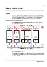
Page 143: ...apter deals with the internal cooling circuit Internal cooling system diagram The following is a diagram of how the coolant circulates in the supply inverter and brake units of a drive system The modules in each cubicle can be isolated from the main cooling circuit by closing the inlet a and outlet valves b Each cubicle is also equipped with a drain valve c and a bleed valve d Supply module A L LC...

Page 144: ...cooling system are listed in Specifications on page 141 Coolant temperature control The temperature of the coolant in the internal cooling circuit must be kept within the limits specified in Specifications on page 141 Note that the minimum temperature is dependent on ambient temperature and relative humidity The following diagram shows an example of coolant temperature control using the three way ...

Page 145: ...e actual bleeding of the circuit must be done via an external bleed valve installed at the highest point of the cooling circuit The most practical location for the valve is usually near or at the cooling unit Observe the instructions given by the manufacturer of the cooling unit Pay special attention to filling up and bleeding the pumps properly as they may be damaged if operated when dry Draining...

Page 146: ...aining the whole internal cooling circuit WARNING High pressure warm coolant may be present in the internal cooling circuit No work on the cooling circuit is allowed until the pressure is lowered down by stopping the pumps and draining coolant 1 Lead the bleed and drain hoses to buckets or other suitable containers Extend the standard hoses if necessary Note Draining propylene glycol into the sewe...

Page 147: ...d by 1 per 1 C temperature increase Maximum inlet temperature variation 4 C Maximum temperature rise 13 C depends on mass flow Pressure limits Base pressure 100 150 kPa recommended 200 kPa maximum Base pressure denotes the pressure of the system compared with the atmospheric pressure when the cooling circuit is filled with coolant Tair C Min Tcoolant C φ 95 φ 80 φ 65 φ 50 φ 40 5 4 3 1 9 0 9 4 5 7 ...

Page 148: ...CI 649 by Cortec Corporation www cortecvci com Glycol concentration The graph below shows the required glycol concentration in weight percentage according to ambient storage temperature T Tap water The use of tap water is allowed as follows Tap water must fulfil the requirements of the Council Directive 98 83 EC of 3 11 98 on the quality of water intended for human consumption Corrosion inhibition...

Page 149: ...erials such as PA PEX and PTFE Note PVC hoses are not suitable for use with antifreeze rubber gasketing NBR nitrile rubber WARNING If connecting external piping to the internal cooling circuit use only materials that are specified above Copper and brass must not be used under any circumstances Even minor dissolution of copper can cause copper precipitation on aluminium and subsequent galvanic corr...

Page 150: ...Internal cooling circuit 144 ...

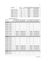
Page 151: ...CS800 17LC 0430 3 625 837 355 600 355 468 250 ACS800 17LC 0580 3 835 1037 500 802 450 625 355 ACS800 17LC 0870 3 1250 1590 710 1200 710 935 500 ACS800 17LC 1130 3 1635 1994 900 1570 900 1223 710 ACS800 17LC 1680 3 2430 2941 1400 2333 1400 1818 1000 ACS800 17LC 2220 3 3210 3906 1800 3082 1800 2401 1400 ACS800 17LC 3300 3 4765 5799 2800 4574 2400 3564 2000 UN 500 V ACS800 17LC 0120 5 139 232 90 133 ...

Page 152: ...1400 1152 1200 ACS800 17LC 2430 7 2035 3350 2000 1954 2000 1522 1600 ACS800 17LC 3620 7 3025 4974 3200 2904 2800 2263 2400 ACS800 17LC 4630 7 3878 5802 4000 3723 3600 2901 2800 ACS800 17LC 5300 7 4432 6630 4400 4255 4000 3315 3200 ACS800 17LC 5960 7 4986 7460 5200 4787 4800 3730 3600 PDM 00430970 Nominal ratings Icont max Continuous rms output current No overloadability at 45 C 113 F Imax Maximum ...

Page 153: ...8i 6 ACS800 104LC 0620 3 E205 6 ACS800 104LC 0620 3 E205 UN 500 V ACS800 17LC 0120 5 R7i R7i 1 ACS800 104LC 0140 5 1 ACS800 104LC 0140 5 ACS800 17LC 0170 5 R7i R7i 1 ACS800 104LC 0170 5 1 ACS800 104LC 0170 5 ACS800 17LC 0210 5 R7i R7i 1 ACS800 104LC 0220 5 1 ACS800 104LC 0220 5 ACS800 17LC 0250 5 R7i R7i 1 ACS800 104LC 0260 5 1 ACS800 104LC 0260 5 ACS800 17LC 0310 5 R8i R8i 1 ACS800 104LC 0380 5 E...

Page 154: ... 690 V ACS800 17LC 0130 7 NBRW 669C SAFUR200F500 107 2 72 ACS800 17LC 0170 7 NBRW 669C SAFUR200F500 107 2 72 ACS800 17LC 0210 7 NBRW 669C SAFUR200F500 107 2 72 ACS800 17LC 0280 7 NBRW 669C SAFUR200F500 107 2 72 ACS800 17LC 0390 7 NBRW 669C SAFUR200F500 107 2 72 ACS800 17LC 0470 7 NBRW 669C SAFUR200F500 107 2 72 ACS800 17LC 0630 7 2xNBRW 669C 2xSAFUR200F500 214 1 36 ACS800 17LC 0950 7 ACS800 17LC 1...

Page 155: ...0520 5 ACS800 607LC 0630 5 310 3 2 2 400 700 ACS800 17LC 0690 5 ACS800 607LC 0630 5 310 3 2 2 400 700 ACS800 17LC 1030 5 ACS800 17LC 1350 5 ACS800 17LC 2000 5 ACS800 17LC 2640 5 ACS800 17LC 3930 5 UN 690 V ACS800 17LC 0130 7 ACS800 607LC 0430 7 155 3 6 400 700 ACS800 17LC 0170 7 ACS800 607LC 0430 7 155 3 6 400 700 ACS800 17LC 0210 7 ACS800 607LC 0430 7 155 3 6 400 700 ACS800 17LC 0280 7 ACS800 607...

Page 156: ...063 PC44UD70V25CTQ ACS800 17LC 2220 3 2903 6 170M7062 PC44UD75V20CTQ ACS800 17LC 3300 3 4309 6 170M7063 PC44UD70V25CTQ UN 500 V ACS800 17LC 0120 5 126 3 170M4409 ACS800 17LC 0170 5 173 3 170M4411 PC31UD69V350TF ACS800 17LC 0210 5 216 3 170M4411 PC31UD69V350TF ACS800 17LC 0250 5 264 3 170M4413 PC31UD69V450TF ACS800 17LC 0310 5 324 3 170M4415 PC31UD69V550TF ACS800 17LC 0410 5 432 3 170M5413 PC32UD69...

Page 157: ...5 PC33UD69V1100TF ACS800 17LC 1130 3 4 170M6419 PC73UD69V1600TF 4 170M6419 PC73UD69V1600TF ACS800 17LC 1680 3 6 170M6419 PC73UD69V1600TF 6 170M6419 PC73UD69V1600TF ACS800 17LC 2220 3 8 170M6419 PC73UD69V1600TF 8 170M6419 PC73UD69V1600TF ACS800 17LC 3300 3 12 170M6419 PC73UD69V1600TF 12 170M6419 PC73UD69V1600TF UN 500 V ACS800 17LC 0120 5 ACS800 17LC 0170 5 ACS800 17LC 0210 5 ACS800 17LC 0250 5 ACS...

Page 158: ...C11CTF 18 170M6549 PC73UD10C11CTF Drive type Height Width Depth Weight mm mm mm kg UN 400 V ACS800 17LC 0110 3 2003 1200 644 950 ACS800 17LC 0140 3 2003 1200 644 950 ACS800 17LC 0170 3 2003 1200 644 950 ACS800 17LC 0200 3 2003 1200 644 950 ACS800 17LC 0260 3 2003 1200 644 1100 ACS800 17LC 0350 3 2003 1200 644 1100 ACS800 17LC 0430 3 2003 1200 644 1100 ACS800 17LC 0580 3 2003 1200 644 1400 ACS800 1...

Page 159: ...17LC 5960 7 2003 7400 644 7500 Drive type Losses Cooling data Noise Ploss total Ploss coolant Ploss air Coolant quantity Massflow Pressure loss kW kW kW l l min kPa dBA UN 400 V ACS800 17LC 0110 3 5 1 5 0 0 1 10 3 41 100 59 ACS800 17LC 0140 3 7 1 7 0 0 1 10 3 41 100 59 ACS800 17LC 0170 3 6 7 6 6 0 1 10 3 41 100 59 ACS800 17LC 0200 3 7 7 7 5 0 1 10 3 41 100 59 ACS800 17LC 0260 3 12 4 12 2 0 2 10 3 ...

Page 160: ... 1 5 0 0 1 10 3 41 100 59 ACS800 17LC 0170 7 7 5 7 4 0 1 10 3 41 100 59 ACS800 17LC 0210 7 7 5 7 4 0 1 10 3 41 100 59 ACS800 17LC 0280 7 12 4 12 1 0 3 10 3 41 100 59 ACS800 17LC 0390 7 15 1 14 8 0 3 10 3 41 100 59 ACS800 17LC 0470 7 19 2 18 8 0 4 10 3 41 100 59 ACS800 17LC 0630 7 21 5 21 0 0 5 10 3 41 100 59 ACS800 17LC 0950 7 35 5 34 8 0 7 16 6 70 100 62 ACS800 17LC 1240 7 40 3 39 5 0 8 16 6 79 1...

Page 161: ...alence table on page 147 The cables enter the breaker cubicle Supply modules Screw size Tightening torque Cable lead throughs 1 R7i 1 R8i M12 70 N m 50 lbf ft 6 Ø60 mm 2 R8i 3 R8i 4 R8i M12 70 N m 50 lbf ft 18 Ø60 mm 6 R8i 10 R8i M12 70 N m 50 lbf ft 27 Ø60 mm Dimensions of input terminal in 600 mm breaker cubicle Dimensions of input busbar in 1000 mm breaker cubicle Dimensions of input terminal i...

Page 162: ...e drive is not equipped with common motor terminal cubicle the motor cables enter the inverter module cubicle s Inverter unit configuration No of busbars Screw size Tightening torque Cable lead throughs R7i n R8i n 3 M12 70 N m 52 lbf ft n 6 Ø60 mm 2 36 Dimensions of output busbar in inverter module cubicle n number of inverter modules ...

Page 163: ...t No of busbars Screw size Tightening torque Cable lead throughs Modules ACS800 17LC type R7i R8i 2 R8i All 3 M12 70 N m 52 lbf ft 9 Ø60 mm 2 36 or 12 Ø60 mm in 400 mm wide cubicles 3 R8i All 3 M12 70 N m 52 lbf ft 4 R8i 5 R8i 690 V 3 M12 70 N m 52 lbf ft 12 Ø60 mm 4 R8i 400 and 500 V 2 3 M12 70 N m 52 lbf ft 18 Ø60 mm 5 R8i 6 R8i 400 and 500 V 2 3 M12 70 N m 52 lbf ft 2 12 Ø60 mm 6 R8i 7 R8i 690 ...

Page 164: ...ge Voltage dips Max 25 Power factor Harmonic distortion Harmonics are below the limits defined in IEEE519 for all Isc IL Each individual harmonic current fulfils IEEE519 table 10 3 for Isc IL 20 Current THD and each individual current harmonic fulfil IEC 61000 3 4 table 5 2 for Rsce 66 The values will be met if the supply network voltage is not distorted by other loads and when the drive operates ...

Page 165: ...potentiometer 1 kohm to 10 kohm Auxiliary power output Voltage 24 V DC 10 short circuit proof Maximum current 250 mA shared between this output and optional modules installed on the RMIO Analog outputs Two programmable current outputs 0 4 to 20 mA RL 700 ohm Resolution 0 1 10 bit Inaccuracy 1 Full Scale Range at 25 C 77 F Temperature coefficient 200 ppm C 111 ppm F max Digital inputs With Standard...

Page 166: ...tributed Drives Communication System 24 V DC power input Voltage 24 V DC 10 Typical current consumption without optional modules 250 mA Maximum current consumption 1200 mA with optional modules inserted The terminals on the RMIO board as well as on the optional modules attachable to the board fulfil the Protective Extra Low Voltage PELV requirements stated in EN 50178 provided that the external ci...

Page 167: ... 6 DI6 7 24VD 8 24VD 11 DIIL 10 DGND2 X23 1 24 V 2 GND X25 1 RO1 2 RO1 3 RO1 X26 1 RO2 2 RO2 3 RO2 X27 1 RO3 2 RO3 3 RO3 Common mode voltage between channels 15 V J1 Test voltage 500 V AC or Jumper J1 settings All digital inputs share a common ground This is the default setting Grounds of input groups DI1 DI4 and DI5 DI6 DIIL are separate insulation voltage 50 V Ground Test voltage 4 kV AC ...

Page 168: ...ng Chemical gases Class 3C2 Solid particles Class 3S2 Boards with coating Chemical gases Class 1C2 Solid particles Class 1S3 Boards with coating Chemical gases Class 2C2 Solid particles Class 2S2 Atmospheric pressure 70 to 106 kPa 0 7 to 1 05 atmospheres 70 to 106 kPa 0 7 to 1 05 atmospheres 60 to 106 kPa 0 6 to 1 05 atmospheres Vibration Marine requirements 1 mm peak value 2 13 2 Hz 0 7g 13 2 100...

Page 169: ...erials are environmentally compatible and recyclable All metal parts can be recycled The plastic parts can either be recycled or burned under controlled circumstances according to local regulations Most recyclable parts are marked with recycling marks If recycling is not feasible all parts excluding electrolytic capacitors and printed circuit boards can be landfilled The DC capacitors C1 1 to C1 x...

Page 170: ... 2 n a n a n a 2 R8i 2 R8i 5 1 5 8 11 6 2 2 4 4 7 3 8 16 2 R8i 2 R8i 5 1 5 8 11 6 2 2 4 4 7 3 8 16 3 R8i 3 R8i 7 3 8 3 17 2 2 4 4 9 5 10 5 21 4 4 R8i 4 R8i 9 5 11 22 2 2 4 4 11 7 13 2 26 4 6 R8i 6 R8i 14 5 16 5 32 5 2 5 5 17 19 37 5 8 R8i 7 R8i 18 21 41 2 5 5 20 5 23 5 46 9 R8i 8 R8i 21 23 46 2 5 5 23 5 25 5 51 10 R8i 9 R8i 23 26 52 2 5 5 25 5 28 5 57 Brake units 3 phase brake units ACS800 607LC 1...

Page 171: ...e IEC 60664 1 2007 Insulation coordination for equipment within low voltage systems Part 1 Principles requirements and tests EN 61800 3 2004 Adjustable speed electrical power drive systems Part 3 EMC product standard including specific test methods EN 61800 5 1 2007 Adjustable speed electrical power drive systems Part 5 1 Safety requirements Electrical thermal and energy EN 61800 5 2 2007 Adjustab...

Page 172: ...omponents are in the scope of the Machinery Directive These functions of the drive comply with European harmonized standards such as EN 61800 5 2 The declaration of conformity for each function is in the appropriate function specific manual Compliance with EN 61800 3 2004 Definitions EMC stands for Electromagnetic Compatibility It is the ability of electrical electronic equipment to operate withou...

Page 173: ...er is required to take measures to prevent interference in addition to the requirements for CE compliance listed above if necessary Note It is not allowed to install a drive equipped with EMC filter E202 on IT unearthed systems The supply network becomes connected to earth potential through the EMC filter capacitors which may cause danger or damage the unit Category C3 The drive complies with the ...

Page 174: ...es is drawn up for the installation A template is available from the local ABB representative 3 The motor and control cables are selected as specified in chapter Planning the electrical installation 4 The drive is installed according to the instructions given in chapter Electrical installation WARNING A drive of category C4 is not intended to be used on a low voltage public network which supplies ...

Page 175: ...fuses given in section Fuses page 150 For installation in Canada branch circuit protection must be provided in accordance with Canadian Electrical Code and any applicable provincial codes To fulfil this requirement use the UL classified fuses given in section Fuses page 150 Power cable selection See chapter Planning the electrical installation page 69 Power cable connections For the connection dia...

Page 176: ... of anti virus programs etc to protect the product the network its system and the interface against any kind of security breaches unauthorized access interference intrusion leakage and or theft of data or information ABB and its affiliates are not liable for damages and or losses related to such security breaches any unauthorized access interference intrusion leakage and or theft of data or inform...

Page 177: ... 17LC 1680 3 2003 2315 3100 3700 400 ACS800 17LC 2220 3 2003 2315 3200 4000 600 ACS800 17LC 3300 3 2003 2315 5000 6000 400 400 UN 500 V ACS800 17LC 0120 5 2003 2315 1200 1500 300 ACS800 17LC 0170 5 2003 2315 1200 1500 300 ACS800 17LC 0210 5 2003 2315 1200 1500 300 ACS800 17LC 0250 5 2003 2315 1200 1500 300 ACS800 17LC 0310 5 2003 2315 1200 1500 300 ACS800 17LC 0410 5 2003 2315 1200 1500 300 ACS800...

Page 178: ...3 2315 7400 8400 400 400 Height 1 Height of the basic bottom entry exit unit Height 2 Height with optional sine output filter E206 Width 1 Width of the basic unit Width 2 Width with optional top exit of cables H353 Width 3 Width of commen motor terminal cubicle option H359 for units with bottom exit of cables Optional auxiliary control cubicle width 400 mm or 600 mm 1 phase brake chopper option D1...

Page 179: ...Dimensions 173 Frame sizes R7i R7i and R8i R8i bottom entry exit ...

Page 180: ...Dimensions 174 Frame sizes R7i R7i and R8i R8i marine units C121 ...

Page 181: ...e contacts can be found by navigating to www abb com searchchannels Product training For information on ABB product training navigate to new abb com service training Providing feedback on ABB manuals Your comments on our manuals are welcome Navigate to new abb com drives manuals feedback form Document library on the Internet You can find manuals and other product documents in PDF format on the Int...

Page 182: ...www abb com drives www abb com drivespartners Contact us 3AUA0000065339 Rev B EN 2016 06 07 ...

Reviews: