Maintenance
133
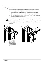
Installing the installation stand
An installation stand for supply and inverter module replacement is available from
ABB as an accessory. The order code is 68847711.
1. Fasten the module installation stand to the frame of the cubicle (2 × 5 screws).
Align the stand and the rails in the cubicle on which the module lies. Adjust the
height of the feet.
Note:
Remove the cabinet hinge first if necessary.
WARNING!
The feet must lean on a solid floor. The cubicle may topple over when
the heavy module is pulled out if the stand is not supported properly.
Do not overtighten (max.
torque 5.5 N·m [4 lbf·ft]).
Ensure that the guide studs
are in frame holes before
tightening screws.
Fixing of triangular support
Brace
Fixing of braces
Slide plane and support feet
Hooks at this end of plate have
to enter holes in frame cabinet.
With these threads it is possible to fix
the unit to the slide plate.
Do not use more than one
slide plate at a time.
These hooks must enter
holes in the brace.
Summary of Contents for ACS800-17LC
Page 1: ...ABB industrial drives Hardware manual ACS800 17LC Drives 55 to 5200 kW ...
Page 4: ......
Page 10: ...Update notice 6 ...
Page 18: ...Table of contents 12 ...
Page 26: ...Safety instructions 20 ...
Page 32: ...Introduction to the manual 26 ...
Page 60: ...Hardware description 54 ...
Page 74: ...Mechanical installation 68 ...
Page 114: ...Electrical installation 108 ...
Page 142: ...Maintenance 136 ...
Page 150: ...Internal cooling circuit 144 ...
Page 179: ...Dimensions 173 Frame sizes R7i R7i and R8i R8i bottom entry exit ...
Page 180: ...Dimensions 174 Frame sizes R7i R7i and R8i R8i marine units C121 ...
Page 182: ...www abb com drives www abb com drivespartners Contact us 3AUA0000065339 Rev B EN 2016 06 07 ...


