FM680 User Manual
r1.7
FM680
Page 9 of 32
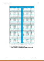
INTER_FPGA_IO12
13 PN4_V
L17
21 BLAST0_VIO
BA25
INTER_FPGA_IO13
13 PN4_V
L16
21 BLAST0_VIO
BA26
INTER_FPGA_IO14
13 PN4_V
G18
21 BLAST0_VIO
BB26
INTER_FPGA_IO15
13 PN4_V
H17
21 BLAST0_VIO
BB27
INTER_FPGA_CLK_A_to_Bn
4 2V5
V7
34 BLAST0_VIO
AY13
INTER_FPGA_CLK_A_to_Bp
4 2V5
V8
34 BLAST0_VIO
AY14
INTER_FPGA_CLK_B_to_An
4 2V5
P9
34 BLAST0_VIO
AP12
INTER_FPGA_CLK_B_to_Ap
4 2V5
R9
34 BLAST0_VIO
AP11
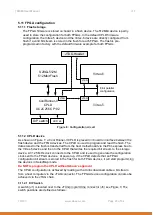
5.3 PCI-express architecture
The Virtex-5 device is connected to the XMC connector (P15) and offers a PCI Express®
Endpoint block integrated in the FPGA. The endpoint will support a 4 lanes generation 1 PCI-
express bus.
A PCI express switch is used to optionally route the 4 lanes from the P15 connector to the
Virtex-6 device instead of the Virtex-5 device. The remaining 4 transceiver lanes on the P15
connector are routed to the Virtex-6 device as well. This makes it possible to have an 8 lanes
generation 1 PCI-express bus connecting to the Virtex-6 device. If this option is selected the
4 lanes connection towards the Virtex-5 device is not available.
The standard reference design has the PCI Express connection towards the Virtex-5 FPGA.
Abaco can provide a reference design for the 8-lanes connection to the Virtex-6 FPGA.
Please consult with your sales contact for more details.
The following performances have been recorded with the FM680 transferring data on the bus
using the standard Abaco PCIe interface design:
PCIe 1 lane: 150Mbytes/s sustained
PCIe 4 lanes: 600Mbytes/s sustained
PCIe 8 lanes: 800Mbytes/s sustained
Higher performance transfers are possible but will require modifications to the PCIe interface
design. Please consult with your sales contact for more details.
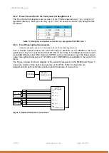
Furthermore the VITA 42.3 standard defines an optional P16 connector which can carry an
additional 8 lanes of high speed signaling. All these lanes are routed to the Virtex-6 device
directly. An overview of the PCI-express subsystem is shown in Figure 3.


