background image


AS2503

AS2603 


DC BRIDGE SYSTEM 

DYNAMIC STRAIN AMPLIFIERS 

INSTRUCTION MANUAL 

1WMPD4003356 

Summary of Contents for AS2503

Page 1: ...AS2503 AS2603 DC BRIDGE SYSTEM DYNAMIC STRAIN AMPLIFIERS INSTRUCTION MANUAL 1WMPD4003356 ...

Page 2: ......

Page 3: ...DC BRIDGE SYSTEM DYNAMIC STRAIN AMPLIFIERS AS2503 AS2603 OPERATION MANUAL Cautions Read this manual carefully before using this product Place this manual within reach of the AS series amplifier ...

Page 4: ......

Page 5: ... surface of the product The warranty does not apply for the case where damages or faults caused by use against instructions warnings or cautions This instrument is delivered after a thorough examination at the factory prior to shipment However please examine the product s condition and verify that no obvious shipping damage has occurred after opening the package Also examine the specifications of ...

Page 6: ...s the following statements are used in this manual to call the readers attention This indicates a condition or practice that could result in personal injury or loss of life and measures and instructions to avoid such conditions This indicates a condition or practice that could result in damage to the instrument or other property and general cautions that users must take into consideration WARNING ...

Page 7: ... protective grounding or protective functions Confirm that there is no failure in the protective function before using Use in Gaseous Atmosphere Never use this amplifier in a flammable or explosive atmosphere or atmosphere of steam Use in such atmosphere will result in danger to users and the amplifiers Input Signal Connection Connect the signal wire to the input terminal after connecting protecti...

Page 8: ...temperature and humidity rise due to direct sunlight or heaters The operating environment of the amplifier temperature 10 to 50 C humidity 20 to 85 2 Wet locations 3 Locations where salt oil or corrosive gases exist 4 Damp or dusty locations 5 Locations subject to strong vibrations 3 Cautions on power supply 1 Be careful of power voltage fluctuations Avoid using the amplifier when the voltage is l...

Page 9: ... a warm room during the cold season open the package after it has reached room temperature to avoid any operational failure due to condensation on the surface of the product Do not use this instrument at the following locations High humidity locations Locations with direct sunlight exposure In the vicinity of high temperature heat source Location with vibrations Locations where salt water oil or c...

Page 10: ...NTY 1 Warranty period Two years from our shipment 2 Warranty limit We will repair the defects of our product free of charge within the warranty period however this warranty does not apply in the following cases 1 Damage or faults caused by incorrect use 2 Damage or faults caused by fire earthquake traffic accident or other natural disasters 3 Damage or faults caused by a repair or modification tha...

Page 11: ...st be disposed of separately from normal household waste This include electrical accessories such as chargers or AC adaptors The mark on the electrical and electronic products only applies to the current European Union Member States Outside the European Union If you wish to dispose of used electrical and electronic products outside the European Union please contact your local authority and ask for...

Page 12: ...ts 9 to 11 1 Overview 1 1 Features 1 1 1 2 Major Features of Amplifiers 1 2 1 3 Accessories 1 2 1 4 Block Diagram of Measurement 1 3 1 5 Features of Dynamic Strain Amplifiers 1 4 2 Names and Functions of Parts 2 1 Names and Functions of Parts on Front Panel 2 1 to 2 5 2 2 How to Set Calibration Value Entering strain 2 6 2 3 How to Set Calibration Value Entering voltage 2 7 2 4 Indication upon Bala...

Page 13: ...e 3 11 to 3 13 3 6 3 Heat Release for Case 3 14 to 3 15 4 Measurement 4 1 Cautions before Measuring 4 1 to 4 2 4 2 Input Connection 4 3 4 2 1 Examples of Strain Gauge Bridge Configurations 4 3 to 4 5 4 2 2 Bridge Box 4 6 to 4 8 4 2 3 Measurement with Transducer 4 8 to 4 9 4 2 4 When using AS Series amplifire as DC amplifire 4 9 to 4 11 4 3 Connection of Output to Load 4 12 4 3 1 Connection of Outp...

Page 14: ... 7 2 How to Replace Fuse 7 3 7 3 Changing AC Power Supply Voltage 7 4 8 Specifications 8 1 AS2503 Specifications 8 1 to 8 3 8 2 AS2603 Specifications 8 4 to 8 6 9 References 9 1 Frequency and Phase Characteristics 9 1 to 9 2 9 2 Cable List 9 3 to 9 4 9 3 External Dimensions 9 5 9 3 1 Amplifier Unit AS2503 9 5 9 3 2 Amplifier Unit AS2603 9 6 9 3 3 Panel Cut Sizes 9 7 9 3 4 Bench top Case 9 8 9 3 5 ...

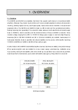
Page 15: ...ranging from 2VDC to 10VDC for bridge power supply is used and high frequency responses DC to 500 kHz in AS2503 and DC to 100 kHz in AS2603 are realized measurement of high speed strain like shocks is possible Also these amplifiers can be used as a DC amplifier featuring 10 000X in AS2503 and 5 000X in AS2603 of the maximum gain Another feature of the AS2503 and AS2603 amplifiers are their lead fr...

Page 16: ...S16 107 8CH Rack mount case Table 1 2 Description of Case 1 3 Accessories Output cord 0311 2057 x 1 Time lag fuse Fuse for AC power supply 85 to 132VAC 180 to 264VAC 125mA 0334 4307 x 1 Fuse for DC power supply 10V to 30VDC 800mA 0334 4315 x 1 Screw driver x 1 AC power cord 0311 5044 Instruction Manual x 1 Model BV Configuration Balance Frequency response Sensitivity at BV 2V Major application AS2...

Page 17: ...ring time Figure 1 1 Block Diagram of Measurement Phenomena Sensor Instrument Recorder Analyzer Oscilloscope Waveform Data Recorder Data Recording Digital Voltage Meter Digital Recording Pen Oscillograph Waveform Rec in Low Freq Range DC 120Hz Thermal Dot Recorder Waveform Rec in High Freq Range DC 20kHz DAQ Waveform Rec in High Freq Range DC 100kHz Data Processor Data Analysis Processing ...

Page 18: ...nsitivity 10 V output in 1 000 10 6 10 V output in 2 000 10 6 Non linearity 0 01 FS 0 05 FS Frequency response DC to 500kHz DC to 100kHz Noise 80 10 6 strain p p 50 10 6 strain p p Maximum gain 10 000X 5 000X Bridge voltage 2 3 5 9 and 10 VDC 2 3 5 9 and 10 VDC Isolation between input block and power supply NA Measurement with strain gauge transducers Measurement of strain such as shock Measuremen...

Page 19: ...LED This level meter monitors the output voltage of OUTPUT1 3 The green LED at the middle comes on when the output voltage is within 100 mV When the output voltage exceeds 10 05 V the LED at the over voltage side blinks Table 2 1 Front Panel Names and Functions 1 f 1 2 3 5 7 4 6 Figure 2 1 AS Amplifier Front View AS2503 Figure 2 2 AS Amplifier Back View ...

Page 20: ...ither disconnection nor short the indication of Good is made thereby making wire length adjustment dropout rate indication and auto balancing If there is a disconnection or short the problematic location is repeatedly indicated After confirming the location make repair For more information on wire disconnection function see pages 3 4 and 3 5 Whenever this button is pressed the resistance balance i...

Page 21: ... sensitivity See page 3 4 for measuring range In this case fine tuning is not made Fine tuning LED comes off Measuring range fine tuning knob FINE Fine tuning is made with the knob Turning the knob clockwise narrows measuring range i e increasing sensitivity and wides the range i e decreasing sensitivity As measuring range fine tuning knob and measuring range selection functions together in AS2503...

Page 22: ...ion value application switch This switch is used to input the value that is set by calibration value setting knob Pushing toward right inputs a plus value tension and pushing toward left inputs a minus value compression As a calibration value is superimposed with the input signal to generate the output voltage return the position to OFF middle after inputting the calibration value High pass filter...

Page 23: ...ol the voltage with the attached screw driver The output value is indicated on the digital monitor As decimal point shifting is possible through the dip switch on the bottom face of the amplifier unit digital monitor can be used for an indicator For how to shift the decimal point refer to page 3 10 Power switch POWER Pressing this switch supply the power to the amplifier unit The power is turned o...

Page 24: ... calibration value repeat the steps above The value is based on the equivalent value for gauge factor 2 00 and one gauge configuration For strain gauge type transducer set and calculate the value based on 1mV V 2000με Calibration value setting Figure 2 4 The fourth digit blinks Press calibration setting knob Turn calibration setting knob to set the value to 5 Press Indication 0 at the first digit ...

Page 25: ...5 6 7 8 9 1 2 3 4 5 6 7 8 9 0 1 2 3 4 5 6 7 8 9 0 1 2 3 4 5 6 7 8 9 0 1 2 3 4 5 6 7 8 9 10 00 99 99 CAL For voltage input mV Figure 2 6 As soon as the fourth digit blinks decimal number digit starts blinking The unit of LED changes from µ to mV Turn and set the value to 8 and then press A value of 2 is illuminated on the second digit and then the first digit blinks Turn to set to 5 and after that ...

Page 26: ...n wire disconnection check is not effective OFF the portions enclosed by broken line are omitted executing auto balancing For how to set these functions to ON or OFF refer to page 3 10 How to Switch Special Function Setting Cable Length Compensation Check ON Figure 2 5 Block diagram for balance operation or Push BAL knob Display bridge check Checking AB line Checking BC line Checking CD line Check...

Page 27: ...e power voltage selection switch BV Selection of power voltage applied to the bridge can be switched 0 5 V or 20 V 3 Output connector 1 OUTPUT1 The output voltage and current are 10 V and 5 mA respectively This connector can be connected to a recorder e g thermal dot recorder or data acquisition devices or A D converter which accept voltage signals Table 2 2 Rear Panel Names and Functions 1 表2 1 前...

Page 28: ...rform keylock auto balancing calibration value application and synchronous signal output A connection cable is available separately Amplifier Interface connector from rear side 1 CAL 2 CAL 3 BAL 4 OSC 5 GND 6 KEYLOCK 7 GND 8 DC 9 DC 6 Protective grounding terminal If 3 pin power cord cannot be used for grounding use this terminal for grounding 7 Power supply connector This is the connector to be c...

Page 29: ...ly Users can change bridge voltage by the voltage pinch on the back panel Bridge supply 2V 3V 5V 9V and 10V Set the slit of the pinch at the number of selected voltage Select Pinch Set the slit of the pinch to select bridge voltage ...

Page 30: ......

Page 31: ... on the rear panel For connection information see Cautions before Measuring on page 4 1 Since the AS2503 and AS2603 automatically adjust the voltage drop generated between the bridge and the amplifier through the wire length adjustment function high accuracy measurement is possible For more information on this adjustment function see page 3 6 Figure 3 1 Connection with bridge box and so on Bridge ...

Page 32: ...e green LED in the middle of level meter Activate for about 10 minutes 5 For correct strain measurement you must conduct initial balancing for the bridge circuit Tune to your target measuring range using measuring range selection knob and adjust the output to zero while no load is being applied 6 Wire disconnection check wire length adjustment and automatic balancing Turn measuring range selection...

Page 33: ...dge is provided after this adjustment As a result high accuracy strain measurement is available without considering the conductor resistance generated by the cable After the wire length adjustment is made the initial balance is made and then the green LED in the middle comes on For further fine tuning turn the BAL knob clockwise or anti clockwise The adjustment range is an output of 1 V The wire l...

Page 34: ... 4 000 1 111 to 2 222 10k 1X to 2X continuous tuning 4 000 to 8 000 2 222 to 4 444 20k 1X to 2 5X continuous tuning 8 000 to 20 000 4 444 to 11 111 50k 1X to 2 5X continuous tuning 20 000 to 50 000 11 111 to 27 777 Measuring Range Measuring Range LED Measuring Range Fine Tuning Knob Measurable Strain 10 6 strain BV 10V 1k 1X to 2X continuous tuning 200 to 400 2k 1X to 2 5X continuous tuning 400 to...

Page 35: ... 20k 1X to 2 5X continuous tuning 8 000 to 20 000 4 444 to 11 111 50k 1X to 2X continuous tuning 20 000 to 40 000 11 111 to 22 222 100k 1X to 2 5X continuous tuning 40 000 to 100 000 22 222 to 55 555 Measuring Range Measuring Range LED Measuring Range Fine Tuning Knob Measurable Strain 10 6 strain BV 10V 2k 1X to 2 5X continuous tuning 400 to 1 000 5k 1X to 2X continuous tuning 1 000 to 2 000 10k ...

Page 36: ...supply is turned off For error contents refer to page 3 5 After confirming the cause of failure take measures to repair the failure Following repairs press the BAL knob for longer than five seconds for disconnection checking If there is no problem Good is indicated If disconnection or a short is detected there is always an error indication However the failure location may not be found depending on...

Page 37: ...da S ab S da S ab S cd S bc S da Disconnection on bridge circuit Disconnection on bridge circuit Error Indication in the case of short Error indication in the case of disconnection Disconnection on cable S ab S bc S cd S da E bc E cd E da or E Lc E Ld E ab E da or E La E ab E bc E cd or E Lb E Lc E ab E bc E da or E La E Lb INDICATION Digital Monitor E ab E cd E da or E La E Ld Disconnection on ca...

Page 38: ...duce measurement time and measurement steps On off for wire length adjustment can be switched using the dip switch on the bottom face of the amplifier See page 3 10 for more details Table 3 4 Rate of Voltage Drop 0 5 mm2 wire at 20 C Figure 3 5 Explanatory Diagram of Wire Length Adjustment Function Distance between amplifier and bridge box m Bridge Resistance 20m 50m 100m 200m 120Ω 1 2 3 0 5 8 11 ...

Page 39: ...ng transducers Resistor for output adjustment in NIPPON AVIONICS s 9E Series transducers Model Resistor Model Resistor Model Resistor Model Resistor 9E01 L1 Provided 9E01 L21 Provided 9E02 P2 Provided 9E08 D1A Provided 9E01 L2 Not provided 9E01 L22 Provided 9E02 P3 Not provided 9E08 D2 Provided 9E01 L3 Provided 9E01 L23 Provided 9E02 P4 Provided 9E08 D3 Provided 9E01 L4 Provided 9E01 L23W Provided...

Page 40: ...gth adjustment function ON Switch 1 down On Wire disconnection check function Switch 2 changeover Wire disconnection check function OFF Switch 2 up Off Wire disconnection check function ON Switch 1 down On Decimal point indication Setup through the combinations of switches 3 and 4 Displaying the decimal point of digital monitor at the third place 100 00 Decimal point indication Setup through the c...

Page 41: ...25 mm2 If eight amplifiers are mounted a current of 3 2 A 0 4 A x 8 flows and a voltage drop of 0 5 V will occur if the cord is extended to 10 m If a 10 m cable with 0 75 mm2 is used a voltage drop of 1 65 V will occur For use under such conditions the power supply should be provided with the voltage drop taken into account or the wire diameter or cord length of the power cord should be modified B...

Page 42: ...balancing is made for all amplifier units This function is available for all amplifier units installed in two or more cases which are connected to each other with a synchronization cable To perform auto balancing for one unit press the BAL knob for that unit Figure 3 8 Rear Panel of case Switch for application of calibration values to all units Switch for balancing for all units Bridge check cable...

Page 43: ...tch for all units positioned in a case BAL knob measuring range selection knob measuring range fine tuning knob calibration value selection knob and filter selection that are positioned on the front panel of each amplifier unit do not function To cancel the key locking hold down the key locking switch for all units In this case if key locking is set in each amplifier unit the key locking status is...

Page 44: ...rack mounting cases In this case install fans following the criteria below because the temperature in the unit rises depending on the number of stacks in the rack load and ambient temperature Floor or Desk Rack mounting case 20mm and over CAUTION Table 3 7 Number of Fan for Heat Release and Rack mount Case Number of case Number of fan unit under severe condition 1 3 1 3 6 2 6 9 3 Note What are har...

Page 45: ...rectly above this position Through this fan layout fan unit A ventilates and fan unit B enhances natural convection One fan unit B should be installed for every three cases It should be mounted as close to a case as possible When a user prepares fans ask NIPPON AVIONICS in advance how to mount the fans 8CH Rack mounting case Cabinet Fan unit A Fan unit B ...

Page 46: ......

Page 47: ... should be as short as possible and should be shielded Prevents reduction in the gauge factor and deterioration in output linearity Prevents noise from entering the equipment The interconnecting cable which connects the bridge box to the AS amplifier unit should be as short as possible The AS amplifier automatically compensates for bridge voltage drops with its cable length compensation Prevents a...

Page 48: ...y of the battery is not correct the amplifier system will not operate However the system and the battery will not be damaged though Do not apply pressure to strain gauges when units are in the auto balancing mode Applying pressure to strain gauges in auto balancing mode causes the bridge to be unbalanced Do not turn the measurement range selector control or the measurement range fine adjustment co...

Page 49: ...utput This section describes examples of bridge configurations that are generally used The following symbols are used R Resistance of fixed register Rg Resistance value of strain gauge Rd Resistance value of dummy gauge r Resistance value of lead wire e Output voltage from bridge V K Gauge factor of strain gauge to be used 2 00 Amount of strain applied m m E Bridge excitation voltage V Poisson s r...

Page 50: ...he calibration value as it is one active gauge one dummy gauge configuration Suited for where simple tension compression or bending force is applied Temperature compensation using a dummy gauge Calculated using the calibration value as it is Two active Gauge configuration Suited for where simple tension compression or bending force is applied Temperature compensation Calculated using calibrated va...

Page 51: ...alibration value x 1 2 or signal value x 1 2 Four active gauge configuration Detects tension and compression strain Eliminates bending strain Temperature compensation Calculated using calibrated value x 1 2 1 or signal value x 1 2 1 Four active Gauge configuration Detects bending strain Eliminates tension and compression strain Temperature compensation Calculated using calibration value x 1 4 or s...

Page 52: ...ridge box in an area as close to the measurement point as possible b The bridge box may be secured with screws using the screw holes shown in Fig 4 1 as needed c Avoid installing the bridge box where it will be exposed to high humidity excessive temperature changes or strong electric and magnetic fields d When the bridge box is installed secure the interconnecting cable if possible and connect it ...

Page 53: ...asurements without having to pay attention to the difference between the output voltage and the calibration CAL value For information on how to correct the value refer to Correction of Calibrated CAL Value on page 4 15 As the amplifier can supply the bridge voltage in which cable conductor resistance is considered thanks to the wire length adjustment function standard accurate measurement can be m...

Page 54: ...and extension cables are manufactured in accordance with the specifications for input connectors of strain gauges specified by the Japanese Society of Non destructive Inspection 2 Operating precautions on use of transducers a Unstable and loose attachment of a transducer may cause malfunctioning of the amplifier unit or noise Transducers should be securely fixed after referring to manufacturer s o...

Page 55: ...ithin 2V 120Ω Within 3V 350Ω Within 10V 500Ω Within 12V 1000Ω Within 12V Table 4 5 Bridge Resistance and Bridge Voltage 4 2 4 When using AS Series amplifier as DC amplifier The AS Series amplifiers are measuring instrument but can be used DC amplifier too 1 When the amplifier is used as DC amplifier using a bridge box In this case CMRR drops slightly Figure 4 5 2 When the amplifier is used as DC a...

Page 56: ...or the relation between input range and gain refer to the following tables AS2503 Measuring range Measuring range LED Measuring range Gain Fine tuning knob Input range Gain 1k 1 2X Continuous tuning 1mV 2mV 10 000X 5 000X 2k 1 2 5X Continuous tuning 2mV 5mV 5 000X 2 000X 5k 1 2X Continuous tuning 5mV 10mV 2 000X 1 000X 10k 1 2X Continuous tuning 10mV 20mV 1 000X 500X 20k 1 2 5X Continuous tuning 2...

Page 57: ...h voltage than those voltages use 1 100 attenuator probe 47322 However the frequency response will be DC to 30 kHz when the attenuator probe is used A calibration value can be applied when the amplifier is used as an DC amplifier For με CAL the amplifier can be used by reading the unit of με as μs by setting BV to 2V ...

Page 58: ...as a physical amount by adjusting the output voltage scaling 4 3 1 Connection of Output to Data Recorder Special care must be taken with the input level of data recorders Especially with frequency modulated data recorders if an input signal greater than the allowable input level of the data recorder is applied it may be overmodulated causing failure in recording To avoid this the amplifier unit is...

Page 59: ...a voltage divider is inserted as shown in Fig 4 7 this will cause errors as described in the following example Example Errors will be caused as shown in Table 4 7 if the voltage dividing ratio is 1 10 under the following conditions Input impedance of data recorder Ri 100 k Ci 100 pF Output impedance of the amplifier unit R0 1 L0 200 H R1 kΩ R2 kΩ Errors caused by voltage divider 5 DC 1kHz 2kHz 5kH...

Page 60: ...f 1 mV V into an amount of strain the rated output is given by 1 mV V x 2V 2mV Where the load cell is used with the bridge voltage E 2V If the measurement is based on the quarter bridge configuration with a gate factor K of 2 00 the relationship between the amount of strain to be applied to the bridge and the output voltage e is given by e 1 4 x K x E x 1 4 x 2 x 2 x That is 1 m m strain correspon...

Page 61: ... this amplifier unit are equivalent voltage values based on the 2 00 gauge factor and the quarter bridge configuration The calibration values based on half or full bridge configurations can thus be obtained by referring to the next table The relationship between the bridge supply voltage and bridge output voltage can be represented by the following formula e K x x E x Bridge configuration 4 Where ...

Page 62: ...he voltage drop rate refer to Bridge Voltage Drop Rate on page 4 7 or measure the voltage drop rate between terminals A and C on the bridge box using a voltmeter Example If the cable length is 100 m and the strain gauge resistance is 120 under an ambient temperature of 20 C the bridge supply voltage will be reduced by 5 8 between terminals A and C which can be obtained from the Bridge Voltage Drop...

Page 63: ... not exceed the common mode voltage 5V 4 5 2 Special use of transducer 1 When calculating value of addition Figure 4 13 Separate power supply is needed for E1 E2 and E3 In this case 50 Hz or 60 Hz noise from commercial power supply will affect the measurement To minimize the influence of the noise add a capacitor 2 When calculating value of subtraction Figure 4 14 Separate power supply is needed f...

Page 64: ...nsducers and special attention is required on capacity of the bridge supply if using dynamic strain measuring equipments E E1 E2 E3 D B C A Dynamic strain amplifier Output D B C A D B C A E E1 E2 D B C A Dynamic strain amplifier Output D B C A Figure 4 13 Figure 4 14 D B C A Dynamic strain amplifier Output D B C A D B C A Figure 4 15 ...

Page 65: ...olated Power Supply I F Connector Level Meter 17 dot LED Digital Monitor Four digits 1 2 LED Operation Key CAL Monitor Analog to Digital Converter B C E D A R BAL CAL AC100V 85 132V AC200V 180 264V SELECT OUTPUT1 OUTPUT2 RANGE ATT RANGE FINE 2nd AMP INPUT Selection CPU HPF LPF 5V HEAD AMP DC12V Level Meter 17 dot LED Digital Monitor Four digits 1 2 LED Operation Key CAL Monitor I F Connector Analo...

Page 66: ... capacitance unbalance auto eliminating circuit C BAL only the signal of which is fed to the subsequent stage The signal which has been amplified through a main amplifier and then outputted via a LPF Low pass Filter and HPF High pass Filter at AS2503 The signal which has been amplified through a main amplifier and then outputted via a signal isolation circuit and LPF and HPF at AS2603 There are tw...

Page 67: ...the panel to the case use top and bottom screws 6 1 3 Connecting Grounding Wire When an amplifier unit is connected to a case the protective grounding terminal case protective grounding terminal grounding terminal of batch power supply connector are connected and have the same potential The grounding wire should have AWG16 wire material and connected with a screw Always connect the grounding wire ...

Page 68: ......

Page 69: ...000 10 6 to 250 000 10 6 strain for AS2603 Check common mode voltage Power supply voltagange 10 to 30VDC 85 to 132VAC 50Hz or 60Hz Does the green LED of level meter come on After adding the dummy resistor to the bridge box set the measurement range selection knob to OFF After that turn to the direction of 1k to perform bridge balancing for each range sequentially Was the bridge balanced Symptom 1 ...

Page 70: ...ss the surface of the strain gauge softly Then does the level of level meter move Yes Remove the strain gauge and paste a new strain gauge Set the measuring range to OFF using measuring range selection knob OFF illuminates on measuring LED Disconnect the bridge circuit from the amplifier unit and then measure the isolation resistance of the bridge circuit No Does the isolation resistance have 60 M...

Page 71: ...er supply fuse When replacing be careful of AC and DC 6 When installing fuse holder use a flat blade screw driver When pushing the fuse keep the fuse holder slit to be vertical to the amplifier unit Figure 7 2 dotted line and then press deeply and turn clockwise by 90 degree 7 Confirm that the fuse holder is fully installed in the amplifier unit as Figure 7 2 Also confirm that the fuse holder slit...

Page 72: ... 100 mA 0334 3006 can therefore be used for both supply voltages 4 Attach the amplifier cover so that the slit of the amplifier cover matches to the frame of the amplifier unit 5 Fasten the screws of upper face The fuse replacement is competed 6 When using 200 VAC power supply use optional AC power supply cord 200 V Figure 7 8 0311 5112 Power cord and input output cable should be disconnected As t...

Page 73: ...alance adjusting accuracy Within 1 0 10 6 in strain RANGE 50k Without FINE BV 2V Maximum input range 125 000 10 6 in strain RANGE 50k FINE 2 5 BV 2V Voltage sensitivity 1 000 10 6 in strain RANGE 1k Without FINE BV 2V Measurement range change 1k 2k 5k 10k 20k 50k 10 6 in strain 2 BV in value OFF Fine adjustment Continuously changeable in FINE RANGE 2 step changing amount can be selected Internal c...

Page 74: ...t Displaying location of decimal point can be changed by using the bottom setting SW Key lock function Turning the key lock ON OFF by pressing the key lock button approximately for one second Except CAL switch and BV selection switch Setting value saving Saving the value in flash memory Can be held without back up battery Resistance to vibration 29 4m s 2 50Hz X Y Z 10 minutes for each and conform...

Page 75: ...olution 0 1 Common mode rejection ratio CMRR 70 dB or more 50 Hz or 60 Hz at 1 k balanced input Maximum allowable input voltage 8 VDC or AC peak value Common mode allowable input voltage 5 VDC or AC peak value Internal calibrator Set value 0 01 to 99 99 mV 0 01 to 59 99 mV at BV 2 V Accuracy 0 2 rdg 5 V Linearity Within 0 01 FS Stability Zero point Within 1 V C 5 V 24 hours Sensitivity Within 0 01...

Page 76: ...usting accuracy Within 2 0 10 6 in strain RANGE 2k Without FINE BV 2V Maximum input range 250 000 10 6 in strain RANGE 100k FINE 2 5 BV 2V Voltage sensitivity 1 000 10 6 in strain RANGE 1k Without FINE BV 2V Measurement range change 2k 5k 10k 20k 50k 100k 10 6 in strain 2 BV in value OFF Fine adjustment Continuously changeable in FINE RANGE 2 step changing amount can be selected Internal calibrato...

Page 77: ...t Displaying location of decimal point can be changed by using the bottom setting SW Key lock function Turning the key lock ON OFF by pressing the key lock button approximately for one second Except CAL switch and BV selection switch Setting value saving Saving the value in flash memory Can be held without back up battery Resistance to vibration 29 4m s 2 50Hz X Y Z 10 minutes for each and conform...

Page 78: ...olution 0 1 Common mode rejection ratio CMRR 70 dB or more 50 Hz or 60 Hz at 1 k balanced input Maximum allowable input voltage 8 VDC or AC peak value Common mode allowable input voltage 5 VDC or AC peak value Internal calibrator Set value 0 01 to 99 99 mV 0 01 to 59 99 mV at BV 2 V Accuracy 0 2 rdg 5 V Linearity Within 0 05 FS Stability Zero point Within 1 V C 5 V 24 hours Sensitivity Within 0 01...

Page 79: ...es of AS2503 400 0 300 0 200 0 100 0 0 0 1 10 100 1000 10000 100000 1000000 Phase Delay Degree 10Hz 30Hz 100Hz 1kHz 30kHz W B 500kHz Frequency Characterristics of AS2503 40 30 20 10 0 10 1 10 100 1000 10000 100000 1000000 Amplitude dB 10Hz 30Hz 100Hz 1kHz 30kHz W B 500kHz ...

Page 80: ...000 1000000 Amplitude dB Frequency Characteristics of AS2603 10Hz 30Hz 100Hz 1kHz 30kHz W B 100kHz 400 0 300 0 200 0 100 0 0 0 1 10 100 1000 10000 100000 1000000 Phase Delay Degree Phase properties of AS2603 10Hz 30Hz 100Hz 1kHz 30kHz W B 100kHz ...

Page 81: ...226 Length 2m Metal BNC Metal BNC Output cable TYPE 0311 5200 Length 2m Insulated BNC Metal BNC For RA connection AC power supply cord For amplifier unit and case 100VAC TYPE 0311 5044 Length 2 5m AS amplifier unit and case attached as standard one AC power supply cord For amplifier unit 200VAC TYPE 0311 5112 Length 3 5m Bare wire DC power supply cord For amplifier unit TYPE AS16 401 Red DC Black ...

Page 82: ... 47231 A BV B Input C BV D Input E Shield Length 25m External diameter of cable Φ9 6 Core wire 0 5mm 2 Synchronization cable Between new cases and new cases TYPE AS16 402 CAL CAL BAL OSC GND KEYLOCK GND DC DC Length 1 8m D Sub9pin male D Sub9pin male Straight cable Non Conection At DC Strain Amplifier wiring is made for only amplifier unit Case connector TABLE 9 1 Cable List 2 ...

Page 83: ...9 5 9 3 External Dimensions 9 3 1 Amplifier Unit AS2503 ...

Page 84: ...9 6 9 3 2 Amplifier Unit AS2603 ...

Page 85: ...9 7 9 3 3 Panel Cut Sizes ...

Page 86: ...9 8 9 3 4 Bench top Case Name Type A B 4CH Bench top case AS16 104 262 6 236 6CH Bench top case AS16 105 362 6 336 8CH Bench top case AS16 106 462 6 436 ...

Page 87: ...9 9 9 3 5 Rack mount Case Rack Rail Elongate Hole ...

Page 88: ...9 10 9 3 6 Bridge Box 5370 and 5373 ...

Page 89: ...take no responsibility for any damages caused by the following reasons 1 Consequential damages and production compensation caused by any accidents of our product 2 Damages of our product generated by other companies equipments and their construction 3 When operation proper maintenance and regular inspection are not done 4 Troubles which are apparently not attributable to our company or those that ...

Page 90: ...in this manual may be updated without prior notice AS2503 AS2603 Operation Manual 1WMPD4003356 First Edition July 2006 Second Edition Octber 2012 Third Edition July 2013 Forth Edition June 2014 Fifth Edition July 2014 Sixth Edition March 2015 Seventh Edition June 2015 Eighth April 2016 ...

Reviews: