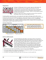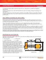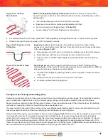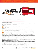
To use the 3M Heat Trace Bill of Materials Tool, visit
3M.ca/HeatTrace
36
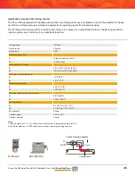
Junction boxes:
KSR™ Self-Regulating Heating Cable power connection and end termination points must be located
inside suitable junction boxes located above the moisture line. Depending on the size of the junction box, several power
connections and/or end terminations can be located within the same box.
• Protect heating cable with rigid metallic conduit (one cable per conduit) between junction box and area being heated
• Extend conduit (equipped with bushings on each end) a minimum of 12" into slab
A typical junction box and conduit assembly is shown in
Figure 3.4.1
.
Note: When calculating the amount of KSR™ Self-Regulating Heating Cable required based on the square footage of the area, allowances should be included for making connections within junction boxes
and for any expansion joint kits necessary to complete the layout.
The total operating load of a KSR™ Self-Regulating Heating Cable Snow and Ice Melting System is dependent on the
supply voltage and the total footage of cable which will be energized. To determine the total operating load, use the
following amps per foot multipliers:
By inserting the appropriate values into the following formula, the total load of the snow and ice melting system can
be determined.
As the example facility will have 208 Vac, single-phase, four-wire available, KSR-2 cable is selected. To optimize
the circuit length potential, the branch circuit breakers will be sized to reflect the layout of the cable (see Step 4
for cable layout).
Design step 4: specify locations for power connections/end terminations and layout cable on
scaled drawing
Total KSR™ Self-Regulating Heating Cable required for area in ft
2 x (12 ÷ S)
and substituting values for the design example:
Total KSR™ Self-Regulating Heating Cable required = 600 ft2 x (12 ÷ 9)
the total footage of cable can be estimated:
Total KSR™ Self-Regulating Heating Cable required = 800 linear feet (plus allowance from Note 2)
Using Formula 3.2:
Pt = Lt x If x E
and substituting values for the design example:
Pt = 840 ft x 0.12 amps/ft x 208 Vac
the total kilowatt demand for the system can be estimated:
Pt = 21 kw
Using Formula 3.1: Putting the Formula to Work
KSR-2 @ 208-240 Vac draws 0.12 amps/foot
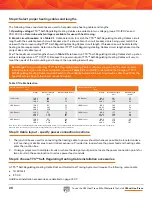
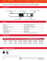
Table 3.3.1: Cable Selection
Catalogue Number
Start-Up
Temperature
Operating Voltage
Installation Method
Maximum Circuit Length vs. Breaker Size
15 Amp
20 Amp
30 Amp
40 Amp
KSR-2
-18°C (0°F)
208 Vac
Direct burial
80 ft (24 m) 105 ft (32 m) 160 ft (49 m)
210 ft (64 m)
KSR-2
-18°C (0°F)
240 Vac
Direct burial
85 ft (26 m) 110 ft (34 m)
170 ft (52 m)
225 ft (69 m)
KSR-2
-7°C (20°F)
208 Vac
Direct burial
85 ft (26 m) 110 ft (34 m)
165 ft (50 m)
220 ft (67 m)
KSR-2
-7°C (20°F)
240 Vac
Direct burial
90 ft (27 m) 120 ft (37 m) 180 ft (55 m)
225 ft (69 m)
Summary of Contents for TTS-5-1-OJ
Page 7: ...To use the 3M Heat Trace Bill of Materials Tool visit 3M ca HeatTrace 7 2 2 2 2 2 3 3 3 3...
Page 8: ...To use the 3M Heat Trace Bill of Materials Tool visit 3M ca HeatTrace 8 Pipe Freeze Protection...
Page 11: ...To use the 3M Heat Trace Bill of Materials Tool visit 3M ca HeatTrace 11 4 5 6 7 9 1 8 3 2...


