To use the 3M Heat Trace Bill of Materials Tool, visit
3M.ca/HeatTrace
To use the 3M Heat Trace Bill of Materials Tool, visit
3M.ca/HeatTrace
45
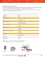
Typical wiring diagram
L1
L2/N
R1-050-DP
Sensor
Heating Cable
R3C-0120-DP
Voltage rating
240 Vac
Switch rating
25 amps
Switch type
DPST
Electrical connection
R1
1
Screw terminals on switch
R3
2
12 AWG leads
Adjustable control range
R1
0°C to 50°C (32°F to 122°F)
R3
0°C to 120°C (32°F to 248°F)
Maximum control differential
R1
1.8°C (32°F)
R3
4.3°C (7.7°F)
Setpoint repeatability
R1
±0.4°C (0.7°F)
R3
±1.1°C (2.0°F)
Maximum bulb exposure temperature
R1
68°C (154°F)
R3
200°C (392°F)
Bulb dimensions
R1
6 x 300 mm (1/4" x 12")
R3
6 x 140 mm (1/4" x 5-1/2")
Bulb material
Copper
Capillary length
300 cm (10')
Capillary material
Copper
Notes:
1. The R1 includes two ½" or ¾" conduit knockouts with an internal grounding terminal.
2. The R3 includes two ½" NPT conduit hubs with an internal grounding terminal.
Application: electric heat tracing control
The R1 and R3, equipped with double-pole switches, are designed for use as adjustable control thermostats for freeze
protection and temperature maintenance applications requiring pipewall or tankwall sensing.
The R1 thermostat is approved for indoor/protected use in ordinary (non-classified) locations. The R3 is approved for
indoor/outdoor use in ordinary (non-classified) locations.
Summary of Contents for TTS-5-1-OJ
Page 7: ...To use the 3M Heat Trace Bill of Materials Tool visit 3M ca HeatTrace 7 2 2 2 2 2 3 3 3 3...
Page 8: ...To use the 3M Heat Trace Bill of Materials Tool visit 3M ca HeatTrace 8 Pipe Freeze Protection...
Page 11: ...To use the 3M Heat Trace Bill of Materials Tool visit 3M ca HeatTrace 11 4 5 6 7 9 1 8 3 2...


