To use the 3M Heat Trace Bill of Materials Tool, visit
3M.ca/HeatTrace
26
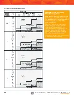
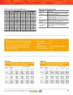
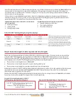
Table 2.1 Cable Selection
Start up temperature 20°F
-7°C
Start up temperature 0°F
-18°C
Voltage
Max Circuit Length
(feet)
Max Ckt Length (meters)
Voltage
Max Circuit Length
(feet)
Max Ckt Length
(meters)
15A Breaker
120 V
208 V
240 V
100
185
190
31
57
58
15A Breaker
120 V
208 V
240 V
80
145
150
25
45
46
20A Breaker
120 V
208 V
240 V
135
245
250
42
75
77
20A Breaker
120 V
208 V
240 V
105
190
200
33
58
61
30A Breaker
120 V
208 V
240 V
175
350
350
54
107
107
30A Breaker
120 V
208 V
240 V
155
290
295
48
89
90
40A Breaker
120 V
208 V
240 V
175
350
350
54
107
107
40A Breaker
120 V
208 V
240 V
175
350
350
54
107
107
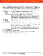
Note: Due to TTS™ Self-Regulating Heating Cable self-regulating feature, TTS™ Self-Regulating Heating Cable will increase power when exposed to ice and snow.
When the cable has cleared the area, the power output will decrease, reducing energy consumption.
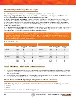
The following three considerations are used to help determine heating cables and lengths:
1. Operating voltage:
TTS™ Self-Regulating Heating Cable
s
are available in two voltage groups: 110-120 Vac and
208-240 Vac.
Determine what voltage is available for use with heat tracing.
2. Branch circuit breakers:
Use
Table
2.1
, Cable Selection, to match the TTS™ Self-Regulating Heating Cable
s
circuit
length with the available branch circuit breaker size. If a known branch circuit breaker size is being used, match this
value with the corresponding TTS™ Self-Regulating Heating Cable
s
circuit length. If breaker size will be dictated by
heating cable requirements, determine the optimal TTS™ Self-Regulating Heating Cable
s
circuit lengths based on the
project size and cable layout.
3. x:
The maximum circuit lengths shown in
Table
2.1
are based on TTS™ Self-Regulating Heating Cable
s
start-up at an
ambient temperature of
7° C (20° F)
. Because the power output of TTS™ Self-Regulating Heating Cables
will vary to
meet the needs of the surrounding environment, the operating load will vary.
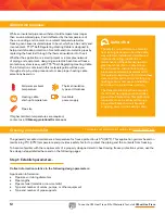
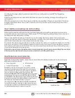
A TTS™ Self-Regulating Heating Cable Roof and Gutter Heat Tracing System will require the following components:
• 18-SXG kit
• ET-4S
Additional installation accessories are detailed on page 41-47.
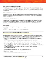
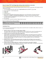
1. The junction boxes used for connecting the heating cable to power should, whenever possible, be located under a
roof overhang or similar area to avoid direct exposure. Provide drip loops where the power feed and heating cable
enter the junction box.
2. On larger projects with multiple circuits or where the design layout permits, locate the power connection points for
two circuits in the same location to reduce power feed conduits.
Step 2: Select proper heating cables and lengths.
Step 4: choose TTS™ Self-Regulating Heating Cable installation accessories.
Step 3: Cable layout - specify power connection locations.
Don’t forget:
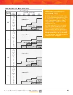
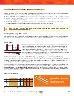
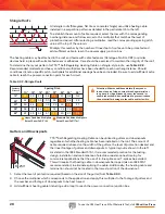
To aid in planning, TTS™ Self-Regulating Heating Cable multipliers are given for the most common
roofing material types. Use these multipliers, shown in
Tables 2.2.1
and
2.2.2
, to determine the footage of TTS™
Self-Regulating Heating Cable required based on the variables indicated. Be sure to add extra cable to get from the
heat-traced area back to the power connection point.
Summary of Contents for TTS-5-1-OJ
Page 7: ...To use the 3M Heat Trace Bill of Materials Tool visit 3M ca HeatTrace 7 2 2 2 2 2 3 3 3 3...
Page 8: ...To use the 3M Heat Trace Bill of Materials Tool visit 3M ca HeatTrace 8 Pipe Freeze Protection...
Page 11: ...To use the 3M Heat Trace Bill of Materials Tool visit 3M ca HeatTrace 11 4 5 6 7 9 1 8 3 2...

