72
C
HAPTER
4: P
OWER
OVER
E
THERNET
C
ONFIGURATION
to guarantee the power feeding to the PD that will be connected to the
Ethernet1/0/24 even when the Switch 4500 PWR is in full load.
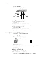
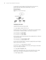
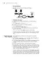
Network Diagram
Figure 17
PoE Remote Power Supply
Configuration Procedure
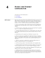
Update the PSE processing software online.
[4500]
poe update refresh 0290_021.s19
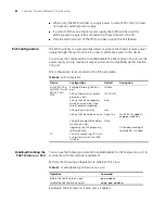
Enable the PoE feature on the Ethernet1/0/1, Ethernet1/0/2, and Ethernet1/0/24
ports (the feature is enabled by default, so this step can be ignored).
[4500-Ethernet1/0/1]
poe enable
[4500-Ethernet1/0/2]
poe enable
[4500-Ethernet1/0/24]
poe enabl
e
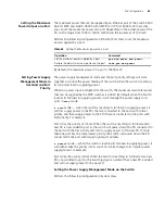
Set the maximum power output of Ethernet1/0/1 and Ethernet1/0/2 to 12000 and
3000 mW respectively.
[4500-Ethernet1/0/1]
poe max-power 12000
[4500-Ethernet1/0/2]
poe max-power 3000
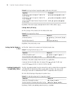
Set the priority of Ethernet1/0/24 to
critical
to guarantee the power feeding to
the AP to which this port connects.
[4500-Ethernet1/0/24]
poe priority critical
Set the power supply management mode on the switch to
auto
(it is the default
mode, so this step can be ignored).
[4500]
poe power-management auto
Enable the PD compatibility detect of the switch to allow the switch to supply
power to part of the devices noncompliant with the 802.3af standard.
[4500]
poe legacy enable
Summary of Contents for 400 Family
Page 12: ......
Page 16: ...14 ABOUT THIS GUIDE ...
Page 58: ...56 CHAPTER 2 PORT OPERATION ...
Page 68: ...66 CHAPTER 3 VLAN OPERATION ...
Page 98: ...96 CHAPTER 5 NETWORK PROTOCOL OPERATION ...
Page 124: ...122 CHAPTER 6 IP ROUTING PROTOCOL OPERATION ...
Page 156: ...154 CHAPTER 8 ACL CONFIGURATION ...
Page 218: ...216 CHAPTER 11 802 1X CONFIGURATION ...
Page 298: ...296 CHAPTER 13 PASSWORD CONTROL CONFIGURATION OPERATIONS ...
Page 336: ...334 APPENDIX B RADIUS SERVER AND RADIUS CLIENT SETUP ...

