8
Deviations of basic parameters
Tripping torque
±12 % of max. value of range
Adjusting speed
- 10 % of max. value of range
+15 % of rated value
(idle run)
Protection
The actuators are fitted with one internal and one external protection terminal for ensuring protection against
electric shock injury according to ČSN 33 2000-4-41. One protection terminal is also installed on the electric motor.
The protection terminals are marked according to ČSN EN 60 417-1 and 2
(013760).
7. DESCRIPTION OF ACTUATOR
The electric actuators are designed for direct mounting on the controlled element. They are connected by a flange and
a clutch according to ČSN 18 6314. The actuator flanges also comply with ISO 5210. The clutches for transmitting motion
to the valve are:
shape A
(with adapter),
according to ISO 5210 and DIN 3210;
shape B1
(with adapter),
according to ISO 5210
(shape B according to DIN 3210);
shape B3
(without adapter),
according to ISO 5210
(shape E according to DIN 3210);
shape D
(without adapter),
according to DIN 3210;
shape C
(without adapter),
according to DIN 3338.
The adapters are fitted between the electric actuator and the valve.
The asynchronous electric motor drives, via a drive gearing, the central wheel of the differential gear located
in the load-bearing box of the electric actuator
(force gear).
In motor control, the crown wheel of the epicyclic differential
is held in constant position by a self-locking screw gear. The hand wheel connected with the screw provides for alternative
manual control even when the electric motor is running, without any danger to the operator.
The output shaft is fix-connected with the epicyclic gear catch driver and passes on to the control box where all
control elements of the actuator are installed.
The control elements are accessible after the control box lid has been removed.
The actuators designated
MONED, MONEDJ are used with electric motors with the protective enclosure IP 55;
the actuators designated
MOPED with electric motors with the protective enclosure IP 67. The complete actuator has
a protective enclosure according to the electric motor used.
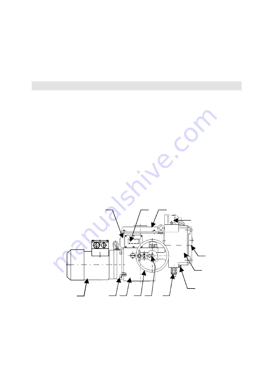
Description:
1 – electric motor
2 – countershaft gear box
3 – power gearing
4 – wheel of manual control
5 – securing screw of hand wheel
6 – cable bushings (connector)
7 – external protective terminal
8 – terminal box
9 – terminal box lid (for DMS2 Analog
and Profibus with local control and display)
10 – block of local control BMO
11 – control box lid
12 – display
13 – control box
Fig. 1 –
Actuator set-up (with electronic system DMS2 ED)
13
12
11
10
9
8
7
6
5
4
3
1
2


