KLIC-DI VRV
http://www.zennio.com
Technical Support:
http://support.zennio.com
5
1.2
INSTALLATION
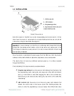
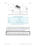
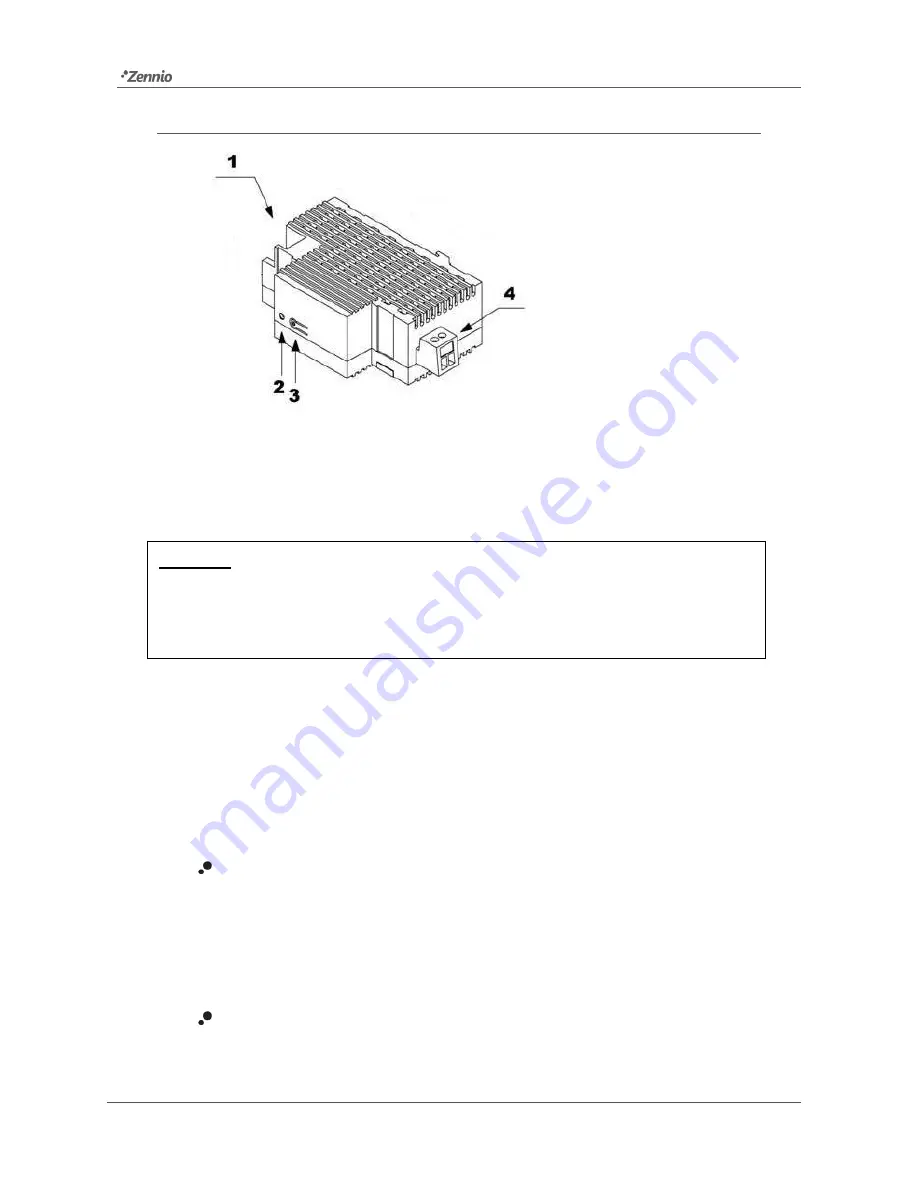
Figure 1.
Element scheme
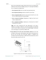
KLIC-DI connects to the KNX bus via the corresponding built-in terminals (1). On the
other hand, this device is connected to the internal PCB board of the A/C unit (P1/P2
connectors), using a 2-wire cable. See Figure 2.
Important
:
in case of aiming to control the air conditioning both through KLIC-DI and
through the incorporated wired remote control of the actual unit, please refer to the
“Control types” subsection, under section 2.2 in order to ensure that both of them have
been properly configured.
Once the device is provided with power supply from the KNX bus, both the physical
address and the desired KLIC-DI application programme can be downloaded.
This device does not need any additional external power as it is entirely powered
through the KNX bus.
The functionality of the main elements is explained below:
Programming button (3)
: a short press on this button will set the device into
the programming mode, making the red component of the LED (2) indicator
light up. If the button is held while plugging the device into the KNX bus,
KLIC-DI will go into secure mode, making the red colour of the LED blink
intermittently.
LED indicator (2)
: three-colour (red, blue and green) light indicator that
reflects the current state of the device. Apart from showing whether the
device is under the programming or secure modes, this LED will also show
1.- KNX connector
2.- LED indicator
3.- Programming button
4.- Input terminal for the two-wire
communication cable.


