INSTRUMENT DESCRIPTION
Carl Zeiss
Operating principle
ApoTome.2
16
423667-7144-001
05/2012
2.5
Operating principle
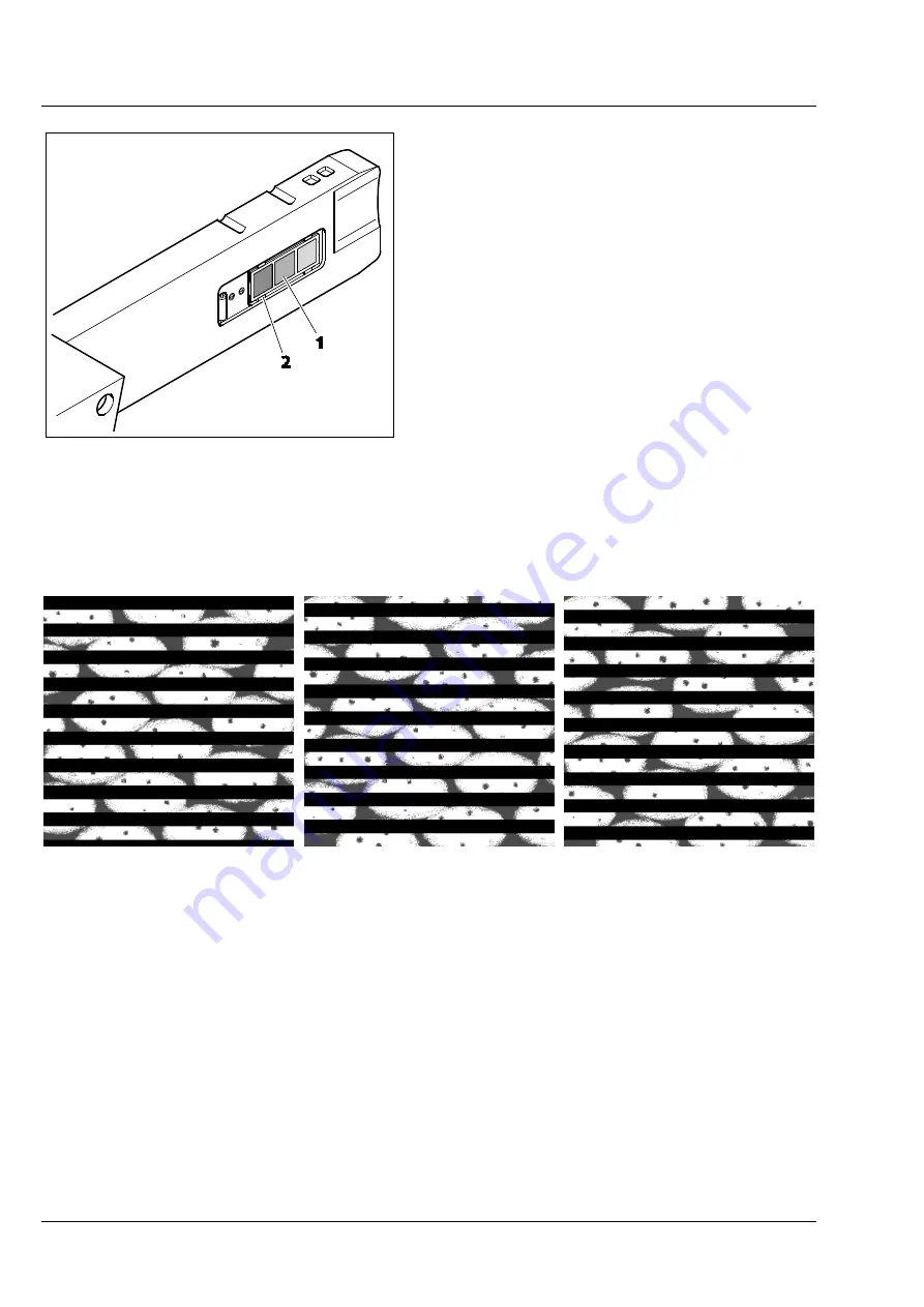
Three different transmission grids (Fig. 2-5/
1
) are
installed in the slider ApoTome.2 on a motorized
changer (Fig. 2-5/
2
). The transmission grids are
three metallic grid structures that are evaporated
on a glass plate.
If the transmission grid is located in the
illumination beam path, the grid structure will be
imaged in the specimen plane. For image capture
the image of the grid structure is shifted in three
defined steps ("phases") in the specimen by means
of a scanner mechanism in ApoTome.2. During this
procedure a given point of the specimen is
illuminated with different intensity depending on
the phase position of the transmission grid.
The three images captured (see Fig. 2-6) with the grid structures are calculated, so that an optical section
with increased contrast and depth discrimination through the specimen will be obtained. The calculation
makes the grid structures of the initial images disappear.
Fig. 2-6
Image capture in three defined steps (phases)
The ApoTome.2 slider is provided with three different transmission grids, which cover the total
magnification range, as indicated in Chapter 2.6. The software automatically recommends the optimal
grid to be used. Optionally, another grid can be selected manually (e.g. to adjust the section thickness to
the experimental conditions).
Please refer to Chapter 2.6 for a precise list about the correct transmission grids for the different
magnifications.
Fig. 2-5
Changer with transmission grids
Содержание ApoTome.2
Страница 1: ...Operating Manual ApoTome 2...
Страница 34: ......


