EM-0146-8
- -
72
■
bit.2 Reserved
This bit is reserved.
* The default setting is “
OFF.
”
■
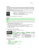
bit.3 Switching combination/single use operation
This bit is used for a model with a controller for combination use to perform single use operation.
* Switching this switch alone does not allow single use operation.
For details, see Section “8.9.”
* The default setting is “
ON
(single use operation mode).”
■
bit.4 Network termination resistor
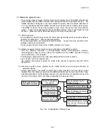
In the combination use operation of the ASE units connected by a communication network, only
one modular cable is connected to each of the AMSE controllers at both ends.
For such AMSE controllers, of which only one port of the modular connector is used, set bit.4
Network termination resistor to “
ON
.” Failure to do so may cause communication errors.
* The default setting is “
OFF
(w/o termination resistor).”
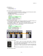
<Example of termination resistor setting>
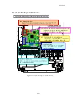
Fig. 8.5c Network Cable Connection
8.5.3 Modular connector (CN3)
This connector is used for connecting modular cables to configure a
communication network connecting between the Master ASE and a slave
ASE unit and between the slave ASE units.
Though, two cable ports are provided, there is no priority order between the
two cable ports. When using only one cable, it can be connected to either
port.
Connect cables, paying attention to the direction of the connector.
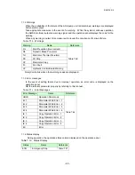
Table 8.5d
ON
/
OFF
Mode
ON
Single use operation
OFF
Combination use operation
Table 8.5e
ON
/
OFF
Mode
ON
w/ termination resistor
OFF
w/o termination resistor
Fig. 8.5d Modular Connector
AMSE (Sn)
AMSE (S2)
AMSE (S1)
AMSE (M)
CN12 CN13
1
2
3
4
SW11
CN12
CN13
1
2
3
4
SW11
CN12
CN13
1
2
3
4
SW11
CN12
CN13
1
2
3
4
SW11
“OFF”
“OFF”
“ON”
“ON”


