Figures and Tables
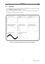
Figure 3-1 Examples of Waveforms Described in This Chapter ......................................... 3-2
Figure 4-1 Waveform Display Screen ................................................................................... 4-2
Figure 4-2 Waveform Editing Operation ............................................................................ 4-14
Figure 5-1 Waveform Generation Screen ............................................................................. 5-2
Figure 5-2 Waveform Generation Screen - Waveform Function ......................................... 5-5
Figure 5-3 Contraction/Extension Screen.......................................................................... 5-11
Figure 5-4 Interpolation Editing Screen ............................................................................. 5-13
Figure 5-5 Inter-Waveform Operation Screen .................................................................... 5-16
Figure 5-6 PWF Screen ....................................................................................................... 5-18
Figure 5-7 System Setup Screen
−
System Setup ............................................................. 5-22
Figure 5-8 System Setup Screen
−
Unit Setup .................................................................. 5-23
Figure 5-9 System Setup Screen
−
Waveform memory Setup .......................................... 5-25
Figure 5-10 System Setup Screen
−
Oscillator Setup ....................................................... 5-27
Figure 7-1 Version Dialog Box .............................................................................................. 7-2
Table 5-1 Parameters for Standard Waveforms ................................................................... 5-4
Table 5-2 Built-in Constants ................................................................................................. 5-6
Table 5-3 Operators ............................................................................................................... 5-7
Table 5-4 Built-in Functions .................................................................................................. 5-8
Table 5-5 Steady Sine Group .............................................................................................. 5-19
Table 5-6 Transient Sine Group .......................................................................................... 5-19
Table 5-7 Pulse Group ......................................................................................................... 5-20
Table 5-8 Transient Response Group ................................................................................. 5-20
Table 5-9 Surge Group ........................................................................................................ 5-20
Table 5-10 Others Group ..................................................................................................... 5-20
Table 5-11 Examples of Custom Units for the Horizontal Axis ......................................... 5-24
Table 5-12 Signal Generator Setting .................................................................................. 5-27
Table 5-13 Initialized Values ............................................................................................... 5-30
Table 6-1 Error Messages ..................................................................................................... 6-2
Page
IM FG410-61EN
vi
Содержание FG410
Страница 1: ...User s Manual FG410 FG420 ARBITRARY WAVEFORM EDITOR IM FG410 61EN 3rd Edition ...
Страница 3: ......
Страница 10: ...1 OVERVIEW 1 1 General 1 2 1 2 Function Tree 1 2 1 3 Conventions 1 5 ARB Edit 1 1 ...
Страница 15: ...1 3 Conventions IM FG410 61EN 1 6 ...
Страница 44: ...4 7 Copy and Paste IM FG410 61EN 4 15 ...
Страница 45: ......
Страница 76: ...6 ERROR MESSAGES 6 1 Arbitrary Wave Edit Software Error 6 2 IM FG410 61EN 6 1 ...
Страница 80: ......
Страница 82: ......
Страница 83: ...https www yokogawa com ymi Yokogawa Test Measurement Corporation ...


