3-22
IM DR231-01E
3.6 Connecting the Power Cable and Turning the Power ON/OFF
DR241 (when connecting wires to screw terminals)
Follow the warnings below to avoid electric shock or damaging the instrument.
WARNING
• Connect the power wires after checking that the power supply is turned
off to prevent electric shock.
• To prevent fire, use 600 V PVC insulated wire (AWG18) for both power
and ground wiring (cross section of 0.83 mm
2
or thicker, anti-galvanic
corrosion finish, insulation thickness more than 0.8 mm, insulation
resistance more than 50 M
Ω
/km at 20
°
C, approved EN60 320
(VDE0625)) for AC power, or equivalent cables. Also use wires with
cross sectional area of 0.3 mm
2
(AWG22) or more for DC power.
• Before turning on the power, always ground the protective ground
terminal so that the grounding resistance is 100
Ω
or less. Do not use
the function grounding terminal (marked terminal) under the power
connecting part as the protective grounding terminal.
• For AC power and ground wiring, use “crimp on” lugs (for 4mm screws)
with insulation sleeves. Make sure that the crimp-on tool must be one
specified by the crimp-on lugs manufacture, and that the crimp-on lugs
and tool must be matched to the wire size.
• To prevent electric shock, do not touch the terminals after wiring.
• Make sure to apply a power switch in the power supply cord with the
following characteristics:
• rated power current > 3 A
• rated rush current > 90 A
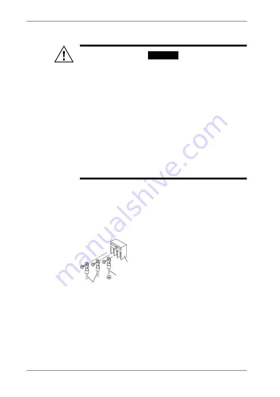
• Connecting procedure for AC power supply
1. Check that the power switch is turned off.
2. Remove the cover protecting the power terminals.
3. Connect the power supply wires and the protecting ground wire to the power terminals.
4. Replace the cover.
Rated supply voltage: 100 to 240 V AC (free power supply),
operating supply voltage: 90 to 250 V AC
Rated supply voltage frequency: 50/60 Hz
Power consumption: About 130 VA max.
L
N
Protective ground wire
Power supply wires
Power terminals
Содержание DR231
Страница 12: ...10 IM DR231 01E...


