6-2
IM DR231-01E
6.1 Setting the Recording Mode/Engineering Unit/Recording Channel and Recording Interval
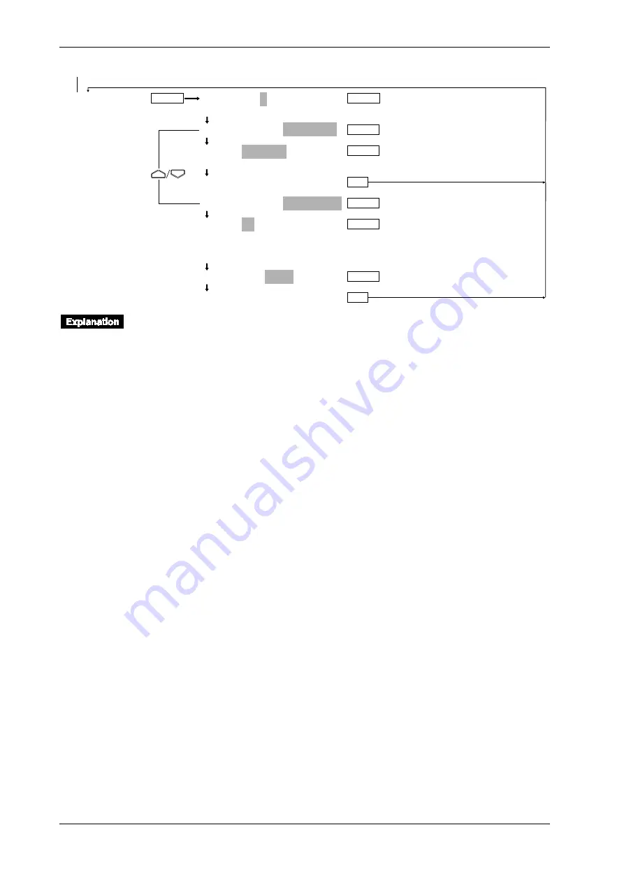
TIMER
TIMER No.=1
1 2 3 4 5 6
1:TIMER MODE=RELATIVE
1:TIME=00 01: 00
>Set DD HH:MM:00
***SET OK***
1:TIMER MODE=ABSOLUTE
1:TIME=1h
1min 2min 3min 4min 5min 6min 10min
12min 15min 20min 30min 1h 2h 3h 4h 6h
8h 12h 24h
1:REF TIME=00:00
***SET OK***
ENTER
ENTER
ENTER
ENTER
ENTER
ENTER
ESC
ENTER
ESC
From the previous page
Recording Mode (SYSTEM)
The following types of recording mode can be selected. The default is TREND.
• LOGGING (LOGGING MODE); measurement values will be printed out as digital values.
• TREND (ANALOG TREND MODE); measurement values will be recorded as analog trends
(trend recording) and printed out as digital values.
• Selecting the recording interval
This setting can only be done for the TREND mode, and its default setting is AUTO.
FIX: recording takes place at intervals equal to the measurement period (scan interval) intervals
AUTO: recording takes place at intervals automatically decided by measurement interval and
chart speed.
Engineering Unit (UNIT)
An engineering unit of up to six characters can be assigned to each channel. The default setting is
all spaces.
The characters/numbers can be selected by cursor from the displayed row on sub-display 1. An
engineering unit can only be assigned to channels to which linear scaling is applied. For details
concerning entering characters/numbers, refer to page 6-15.
If the instrument is equipped with the optional computation function or floppy disk drive, make
sure that channel Nos. are set between A01 and A30 when specifying the measurement units for
computation channels.
Setting the Channels to be Recorded (TREND)
Trend recording
Recording can be set ON/OFF per channel. The default setting is ON.
ON: recording will take place;
OFF: recording will not take place.
The display will show “
■
” for channels set to ON, and “
■
” for channels set to OFF. Refer to
page 4-10 on which channel is being displayed.
If you are installing optional computation channels, channel Nos. must be set to A01 to A30.
Digital Printout in the Analog Trend Mode
Refer to 6.4 Setting Tag, Digital Printout and Manual Printout on page 6-9.
Содержание DR231
Страница 12: ...10 IM DR231 01E...


