76
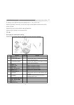
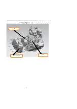
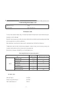
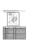
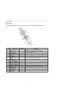
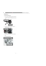
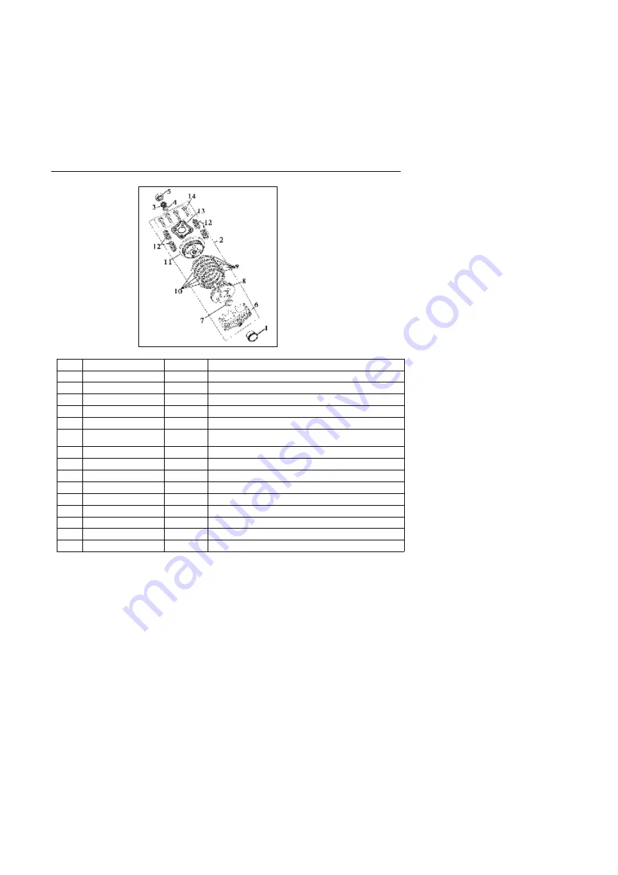
Removal / Installation of Clutch
No
Procedure
Quantity
Remarks
Removing order
Installation is in the reverse order of removal
1
clutch bush
1
Tightening torque 12N.m.
2
clutch assembly
1
3
Nut M14*1
1
4
Flat washer
1
5
Deep
groove
ball
bearing
1
Gum base, soaking oil while assembling
6
Clutch out cover
1
7
Clutch lug washer
1
8
Clutch center bush
1
9
Clutch friction plate
5
10
clutch driven plate
4
Assemble with the sub stage side facing inwards
11
Clutch platen
1
12
Clutch spring
4
13
Clutch plate
1
14
Bolt m6*25
4
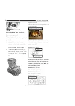
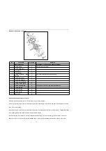
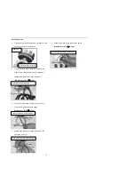
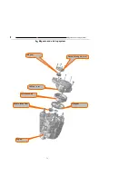
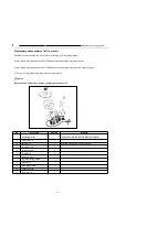
Disassemble and assemble of clutch
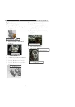
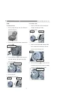
Disassemble and assemble the clutch according to the following diagram.
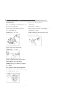
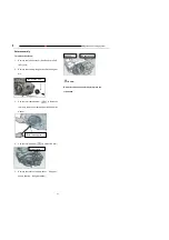
While removing the clutch lift plate, alternatively loosen the 6connecting bolts to avoid damage of cracking due to uneven
force of the clutch spring.
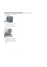
While mounting the clutch lift plate, alternatively loosen the 6 connecting bolts to the specified torque
.
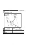
Assemble with
the protruding side of the butterfly washer facing the plain washer
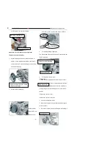
While assembling, the clutch disc must be coated with lubricating oil; in case of replacing new clutch disc, it must be
soaked in oil for over 24 hours before being assembled.
Do not further disassemble the clutch housing, otherwise
Содержание YG125-30B
Страница 44: ...YG125 30B Maintenance Manual Removal and installation of engine 46 5 Removal and installation of engine...
Страница 99: ...YG125 30B Maintenance Manual Frame and exhaust system 106 10 Frame and exhaust system...
Страница 116: ...YG125 30B Maintenance Manual Rear wheel and rear suspension device 122 12 Rear wheel and rear suspension device...
Страница 130: ...YG125 30B Maintenance Manual Illumination signal system 136 Circuit schematic drawing...
Страница 141: ...YG125 30B Maintenance Manual Engine management system 147 Circuit schematic drawing...
Страница 151: ...YG125 30B Maintenance Manual Electrical System Diagram 157 19 Electrical System Diagram...

