YG125-30B
Maintenance Manual
Front wheel, front suspension device and steering stem
115
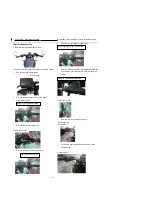
Control subassembly
1
、
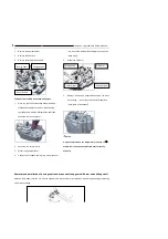
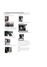
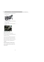
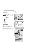
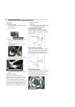
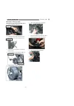
Remove the left/right balance weight.
2
、
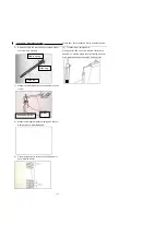
Remove the right handle and right combination switch
l
Pull off the brake switch leads
l
Remove the upper/lower body of the right
combination switch
l
Remove the throttle control line
l
Remove the right combination switch
l
Remove the right brake cylinder body.
l
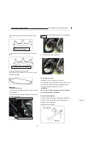
Remove the clutch control line and disassemble the
connection of the clutch switch leads and the main
cable.
l
Remove the left combination switch.
l
Loosen the retaining bolt and remove the clutch
handle holder.
Brake switch
Remove the upper/lower body
Throttle control line
Right combination switch
Remove the right brake cylinder body
Remove the left combination
Clutch control line
Retaining bolt
Remove the left
combination
Содержание YG125-30B
Страница 44: ...YG125 30B Maintenance Manual Removal and installation of engine 46 5 Removal and installation of engine...
Страница 99: ...YG125 30B Maintenance Manual Frame and exhaust system 106 10 Frame and exhaust system...
Страница 116: ...YG125 30B Maintenance Manual Rear wheel and rear suspension device 122 12 Rear wheel and rear suspension device...
Страница 130: ...YG125 30B Maintenance Manual Illumination signal system 136 Circuit schematic drawing...
Страница 141: ...YG125 30B Maintenance Manual Engine management system 147 Circuit schematic drawing...
Страница 151: ...YG125 30B Maintenance Manual Electrical System Diagram 157 19 Electrical System Diagram...

