YG125-30B
Maintenance Manual
Rear wheel and rear suspension device
126
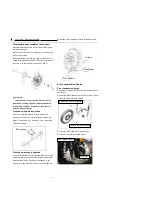
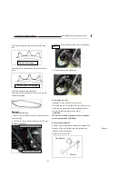
Take out bush and dismantle bolt of rear driven chain
disc.
Check rear driven chain disc whether it is exceed limit
value.
Check chain abrasion and deformation.
Check chain joint pin whether is loose or worn and clip
whether is deformed
Rear fork
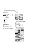
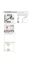
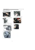
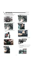
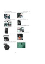
To remove the rear fork:
1
、
Remove the rear wheel assembly first (See
“
Removal
of rear wheels
”
).
2
、
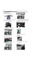
Unscrew the rear fork shaft nuts and pull out the rear
fork shaft from the left
3
、
Remove the rear damper and rear fork connecting bolt.
4
、
Take out the rear fork backwards.
To install the rear fork:
I
nstallation is in the reverse order of removal..
While installing the rear fork shaft, make sure that the end
covers shall be aligned and that the tightening torque of
the rear fork shaft retaining nut is 50-60N.m,
Warning:
The rear fork retaining nut must be firmly screwed up
to the required torque of 50-60N.m.
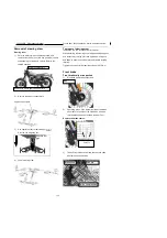
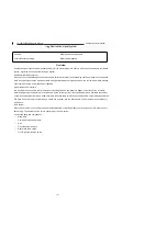
Rear fork shaft inspection
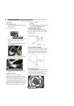
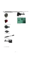
Place the rear fork shaft on the V-holder, and measure the
deflection of the rear fork shaft with a dial gauge; if the
reading is no less than 0.2mm,
Replace the rear fork shaft.
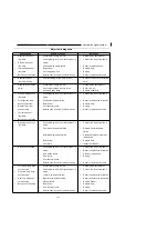
Normal tooth shape
Seriously worn tooth shape
Unscrew the rear fork shaft nuts
Pull out the rear fork shaft
Rotate it
Rotate it
Dial indicator
Bolt
Содержание YG125-30B
Страница 44: ...YG125 30B Maintenance Manual Removal and installation of engine 46 5 Removal and installation of engine...
Страница 99: ...YG125 30B Maintenance Manual Frame and exhaust system 106 10 Frame and exhaust system...
Страница 116: ...YG125 30B Maintenance Manual Rear wheel and rear suspension device 122 12 Rear wheel and rear suspension device...
Страница 130: ...YG125 30B Maintenance Manual Illumination signal system 136 Circuit schematic drawing...
Страница 141: ...YG125 30B Maintenance Manual Engine management system 147 Circuit schematic drawing...
Страница 151: ...YG125 30B Maintenance Manual Electrical System Diagram 157 19 Electrical System Diagram...

