
YG125-30B Maintenance Manual
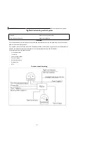
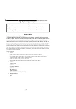
Engine management system
151
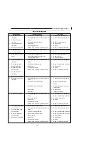
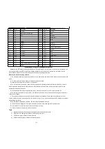
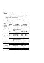
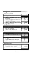
Malfcode
:
P0113
Information
:
IAT Circuit High Voltage
ITEM
OPERATION
RESULT
NEXT STEP
1
Connect the diagnostic tool, and ignition on.
Next
2
check whether the data of
‘
intake air temperature
’
equals to the real intake
air temperature.
Yes
Setp 5
No
Next
3
Remove the connector, and use the multimeter to check whether the
resistance between pin B and D is reasonable according to the temperature.
Yes
Step 5
No
Next
4
Remove the connector and check whether the voltage between pin B and D
is about 5V.
Yes
Next
No
Check harness
5
Check whether the following pins are short to ground or open: J2-8, J2-10 of
the ECU and pin C, D of the connector.
Yes
Change the harness
No
Next
6
Crank the engine and stay idle. Check whether the
‘
intake air temperature
’
goes up when the engine temperature goes up.
Yes
Help
No
Change the sensor.
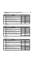
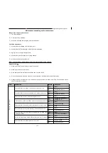
Malfcode
:
P0117
Information
:
Coolant/Oil Temperature Sensor Circuit Low Voltage
ITEM
OPERATION
RESULT
NEXT STEP
1
Connect the diagnostic tool, and ignition on.
Next
2
check whether the data of
‘
engine temperature
’
equals to the real
temperature.
Yes
Step 5
No
Next
3
Remove the connector and use the multimeter to check whether the
resistance between pin A and C of the sensor is reasonable according to the
temperature.
Yes
Step 5
No
Next
4
Use the multimeter to measure whether the voltage between A and C is
about 5V.
Yes
Next
No
Check the harness
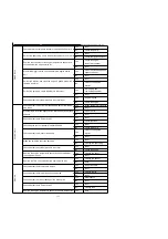
5
check whether the following pins are short to gound or open: J2-10, J2-14 of
the ECU and pin C and D of the sensor.
Yes
Harness issue
No
Next
6
crank the engine and stay idle. Check whether the
‘
engine temperture
’
goes
high when engine get warm.
Yes
Help
No
Change the sensor
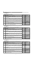
Malfcode
:
P0118
Information
:
Coolant/Oil Temperature Sensor Circuit High Voltage or Open
ITEM
OPERATION
RESULT
NEXT STEP
1
Connect the diagnostic tool, and ignition on.
Next
2
check whether the data of
‘
engine temperature
’
equals to the real
temperature.
Yes
Step 5
No
Next
3
Remove the connector and use the multimeter to check whether the
resistance between pin A and C of the sensor is reasonable according to the
temperature.
Yes
Step 5
No
Next
4
Use the multimeter to measure whether the voltage between A and C is
about 5V.
Yes
Next
No
Check the harness
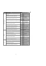
5
check whether the following pins are short to battery or open: J2-10, J2-14
of the ECU and pin C and D of the sensor.
Yes
Harness issue
No
Next
6
crank the engine and stay idle. Check whether the
‘
engine temperture
’
goes
high when engine get warm.
Yes
Help
No
Change the sensor
Содержание YG125-30B
Страница 44: ...YG125 30B Maintenance Manual Removal and installation of engine 46 5 Removal and installation of engine...
Страница 99: ...YG125 30B Maintenance Manual Frame and exhaust system 106 10 Frame and exhaust system...
Страница 116: ...YG125 30B Maintenance Manual Rear wheel and rear suspension device 122 12 Rear wheel and rear suspension device...
Страница 130: ...YG125 30B Maintenance Manual Illumination signal system 136 Circuit schematic drawing...
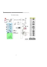
Страница 141: ...YG125 30B Maintenance Manual Engine management system 147 Circuit schematic drawing...
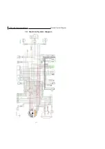
Страница 151: ...YG125 30B Maintenance Manual Electrical System Diagram 157 19 Electrical System Diagram...


