YG125-30B
Maintenance Manual
Cylinder Head, Cylinder and Piston
64
Piston
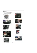
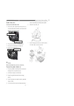
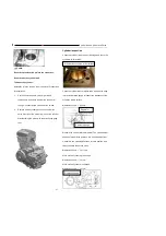
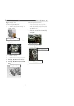
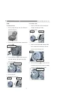
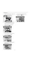
To remove the piston:
1.
Remove the cylinder head cover (See Removal of
cylinder head cover)
2.
Remove the camshaft (See Removal of camshaft).
3.
Remove the cylinder head (See Removal of cylinder
head).
4.
Remove the cylinder (See Removal of cylinder)
5.
Remove the piston pin retainer at one side, and pull
out the piston pin.
6.
Take out the piston.
Notice:
Do not drop the piston pin retainer into the crankcase.
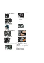
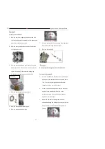
To mount the piston pin:
1.
Coat engine oil on the piston pin surface and let the
oil go through the piston and the small end bore of
the crankshaft link rod.
2.
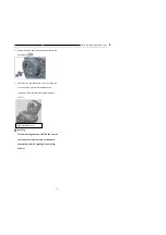
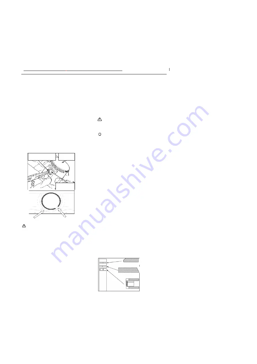
Mount the new piston pin retainer, with the gap
staggering the piston gap by more than 15
°
as
shown in the above.
3.
Mount the cylinder (See Installation of cylinder).
4.
Mount the cylinder head (See Installation of cylinder
head);
5.
Mount the camshaft (See Installation of camshaft).
6.
Mount the cylinder head cover (See Installation of
cylinder head cover).
Notice:
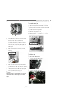
Assemble the piston with the top side with the marker
“ ”
facing exhaust side.
Do not drop the piston pin retainer into the crankcase.
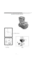
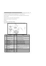
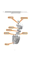
Disassembly and assembly of piston:
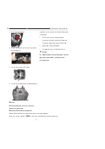
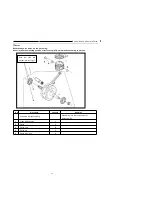
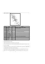
Disassemble and assemble piston according to the
following diagram.
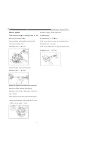
While assembling, let the side with marker face the top of
piston; if the marker can not be clearly
identified, judge according to the shape of the piston ring
(as shown in the figure below).
Stagger the piston ring
gap by more than 120
º
While assembling the oil ring, mount the corrugated ring
first, then mount the lip rings at both sides, with the
corrugated ring joint staggering with both lip rings by
90
°
, and with the two lip rings staggering with each
other by 180
°
The piston pin retainer shall be replaced with new one
while assembling after disassembling, and stagger the
gap and the piston notch by more than 15
°
.
Piston
Piston pin
Piston pin retainer
Piston notc
h
Piston pin retainer gap
First ring
Second
Oil Ring
Содержание YG125-30B
Страница 44: ...YG125 30B Maintenance Manual Removal and installation of engine 46 5 Removal and installation of engine...
Страница 99: ...YG125 30B Maintenance Manual Frame and exhaust system 106 10 Frame and exhaust system...
Страница 116: ...YG125 30B Maintenance Manual Rear wheel and rear suspension device 122 12 Rear wheel and rear suspension device...
Страница 130: ...YG125 30B Maintenance Manual Illumination signal system 136 Circuit schematic drawing...
Страница 141: ...YG125 30B Maintenance Manual Engine management system 147 Circuit schematic drawing...
Страница 151: ...YG125 30B Maintenance Manual Electrical System Diagram 157 19 Electrical System Diagram...

