


6
-14
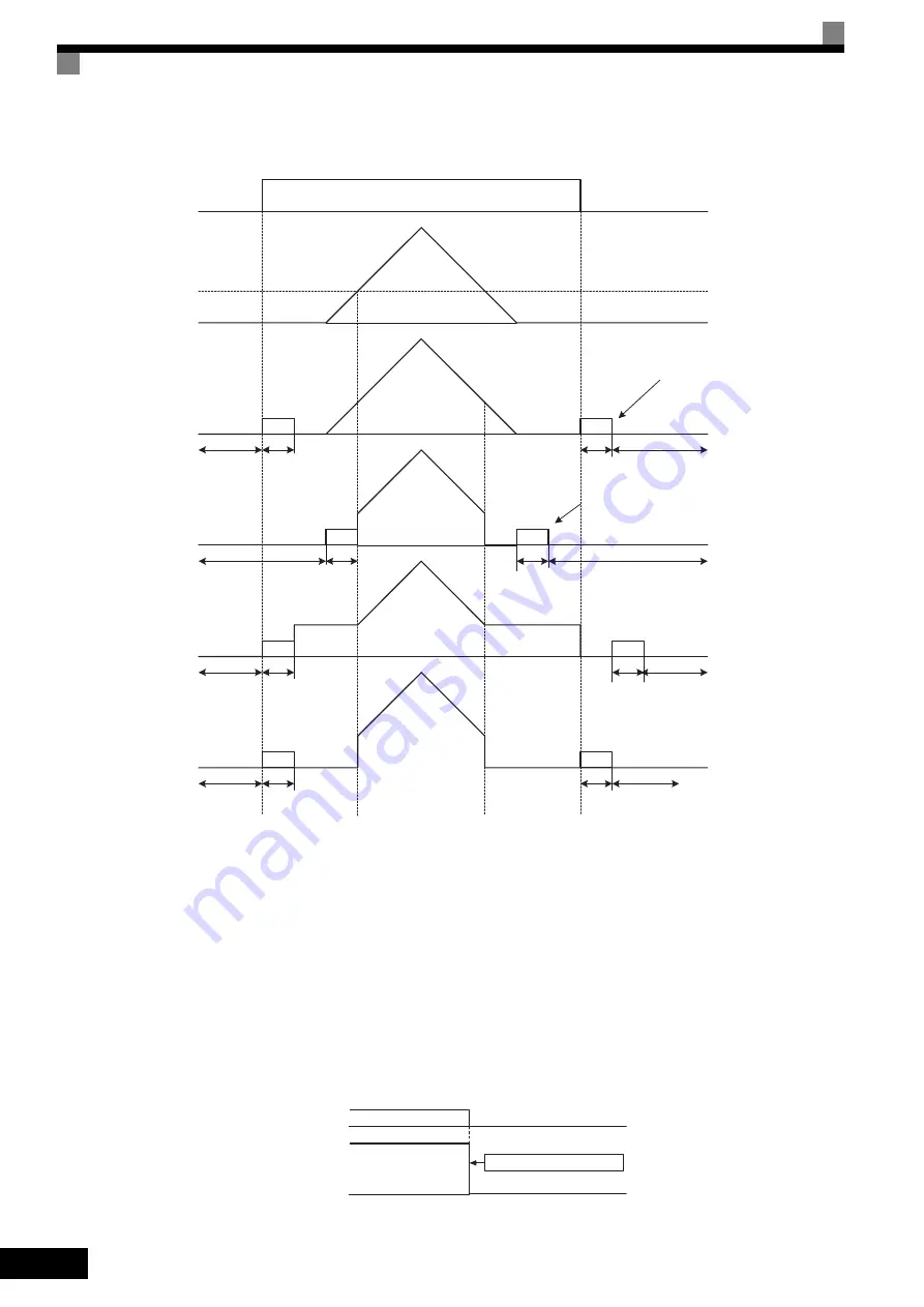
The operation after stopping depends on the setting of b1-05 when flux vector control is selected (A1-02 = 3).
Fig 6.14 Deceleration to Stop (for Flux Vector Control)
Setting Precautions
•
When using flux vector control, the zero-speed control starts when motor speed drops to b2-01 during
deceleration. Also, the setting b2-01
<
E1-09 is possible.
•
The current level during injection brake time at start is the value of E2-03 (motor no-load current). Accord-
ingly, b2-02 is invalid in flux vector control.
Coast to Stop
If the Stop Command is input (i.e., the Run Command is turned OFF) when b1-03 is set to 1, the Inverter out-
put voltage is interrupted. The motor coasts to a stop at the deceleration rate that counterbalances damage to
the machine and inertia including the load.
Fig 6.15 Coast to Stop
Injection brake
time at start
b2-03
Zero speed
control
b2-04
Baseblock
b2-03
b2-04
b2-03
b2-04
b2-03
b2-04
Run Command OFF
ON
OFF
Frequency reference
via analog input
0
E1-09
b1-05=0
(frequency reference)
Run Command turns OFF
and zero-speed control start
when motor speed drops to b2-01.
b1-05=1
(Coast)
b1-05=2
(Run on E1-09)
b1-05=3
(Zero-speed)
Injection brake
time at start
Injection brake
time at start
Injection brake
time at start
Baseblock
Baseblock
Baseblock
Baseblock
Baseblock
Baseblock
Baseblock
Zero speed
control
Zero speed control
Zero speed control
Frequency reference drops to less
than E1-09 and zero-speed control
starts when motor speed drops to
b2-01.
Run Command turns OFF
and zero-speed control start
when motor speed drops to b2-01.
Run Command turns OFF
and zero-speed control start
when motor speed drops to b2-01.
Output frequency
Run Command
ON
OFF
Inverter output freqeuencty interrupted.