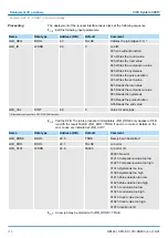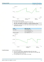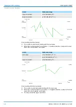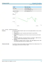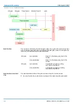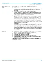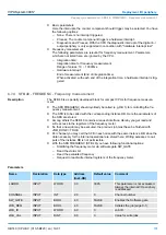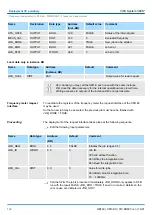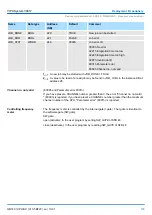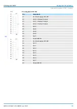
You pre-define the behavior of the counter output via the parameterization:
n
No comparison
The output is set as normal output. The SFB input parameter CTRL_DO is effect less.
The status bits STS_DO and STS_CMP (Status comparator in the instance DB)
remain reset.
n
Count
³
comparison value respectively Count
£
comparison value
The output remains set as long as the counter value is higher or equal comparison
value respectively lower or equal comparison value. For this the control bit must be
set. The comparison result is shown by the status bit STS_CMP. This status bit may
only be reset if the comparison condition is no longer fulfilled.
n
Pulse at comparison value
When the counter reaches the comparison value the output is set for the parameter-
ized pulse duration. If you have configured a main count direction the output is only
activated when the comparison value is reached with the specified main count direc-
tion. For this the control bit CTRL_DO should be set first. The status of the digital
output may be shown by the status bit ST_DO. The comparison result is shown by
the status bit STS_CMP. This status bit may only be reset if the pulse duration has
run off. comparison condition is no longer fulfilled. With pulse time = 0 the output is as
set as the comparison condition is fulfilled.
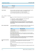
Pulse duration
For adaptation to the used actors a pulse duration may be specified. The pulse dura-
tion defines how long the output should be set. It may be preset in steps of 2ms
between 0 and 510ms. The pulse duration starts with the setting of the according dig-
ital output. The inaccuracy of the pulse duration is less than 1ms. There is no past
triggering of the pulse duration when the comparison value has been left and reached
again during pulse output. A change of the pulse period during runtime is not applied
until the next pulse.
n
The
hysteresis
serves the avoidance of many toggle processes of the output and the
interrupt, if the
counter value
is in the range of the
comparison value
.
n
For the
hysteresis
you may set a range of 0 to 255.
n
The settings 0 and 1 deactivate the
hysteresis
.
n
The
hysteresis
influences zero run, comparison, over- and underflow.
n
An activated
hysteresis
remains active after a change. The new
hysteresis
range is
activated with the next
hysteresis
event.
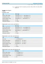
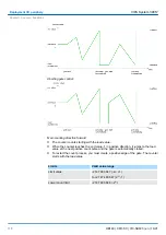
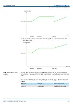
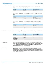
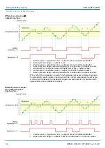
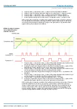
The following pictures illustrate the output behavior for
hysteresis
0 and
hysteresis
3 for
the according conditions:
Characteristics of the
output
Hysteresis
VIPA System 300S
+
Deployment I/O periphery
Counter > Counter - Additional functions
HB140 | CPU-SC | 313-5BF23 | en | 19-01
125


