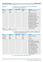
Parameters
Description
Range of values
Default
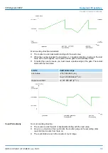
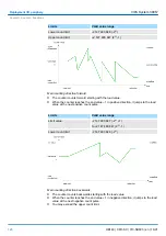
Main count direction
n
None:
No restriction of the counting range
n
Up:
Restricts the up-counting range.
Counter starts at 0 or load value, counts in
positive direction up to the declaration end
value -1 and then jumps back to load value
at the next positive transducer pulse.
n
Down:
Restricts the down-counting range.
The Counter starts at the declared start
value or load value in negative direction,
counts to 1 and then jumps to start value
at the next negative encoder pulse.
n
None
n
Up
n
Down (not with
continuous count)
n
None
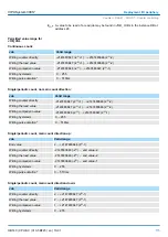
End value/ Start value
End value
, with up-count as default.
Start value
, with down-count as default.
2...2147483647
(2
31
-1)
2147483647 (2
31
-1)
Gate function
n
Cancel count:
The count starts when the
gate opens and resumes at the load value
when the gate opens again.
n
Stop count:
The count is interrupted when
the gate closes and resumed at the last
actual value when the gate opens again.
n
Abort the count
operation
n
Interrupt the count
operation
Cancel count
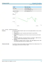
Comparison value
The count value is compared with the compar-
ison value. see also the parameter "Character-
istics of the output":
n
No main direction of count
n
Up-count as default
n
Down-count as default
-2
31
to +2
31
-1
-2
31
to End value
1 to +2
31
-1
0
Hysteresis
A hysteresis is used to eliminate frequent
output jitter if the count value lies within the
range of the comparison value.
0 and 1 means: Hysteresis switched off
0 to 255
0
max. frequency:
counting signals/hard-
ware gate
You can set the maximum frequency of the
track A/pulse, track B/direction and hardware
gate signals in fixed steps.
60, 30, 10, 5, 2, 1kHz
30kHz
max. frequency: Latch You can set the maximum frequency of the
latch signal in fixed steps.
60, 30, 10, 5, 2, 1kHz
10kHz
Signal evaluation
The count and direction signals are connected
to the input.
A rotary transducer is connected to the input
(single, dual or quadruple evaluation).
n
Pulse/Direction
n
Rotary encoder
single
n
Rotary encoder,
double
n
Rotary encoder
quadruple
Pulse/Direction
Hardware gate
In the activated state the Gate control is made
via SWgate and HW-gate, otherwise via SW-
gate only.
n
activated
n
deactivated
deactivated
Count direction
inverted
In the activated state the "direction" input
signal is inverted.
n
activated
n
deactivated
deactivated
VIPA System 300S
+
Deployment I/O periphery
Counter > Counter - Fast introduction
HB140 | CPU-SC | 313-5BF23 | en | 19-01
110


