background image

11 

3.


Description and Function of Each Part 

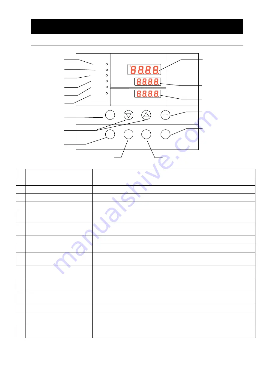
Operation  Panel 


  START/STOP Key 

Start/stop the operation. 

  ▲▼ Key 

Use for rising UP/lowering DOWN the setting value. 

  ENTER Key 

Settle the inputted value. 

  FIXED TEMP Key 

Choose the fixed temperature operation. 

  TIMER Key 

Choose the timer operation (Quick Auto Stop/Auto Stop/Auto Start). 

  PROGRAM Key 

Choose  the  program  operation  or  program  creation  mode.  (3  types  and  6 
modes programs) 

  SUBMENU Key 

Use  for  setting  the  overheating  prevention  temperature,  calibration  offset 
temperature, key lock function, or program repeat function. 

  HEATER Lamp 

Light while the heater works. 

  ALARM Lamp 

Light up when an error occurs. (Buzzer sounds simultaneously.) 

  AUTO STOP Lamp 

Blink while setting quick auto stop timer or auto stop timer. 
Light while quick auto stop timer or auto stop timer is running. 

  AUTO START Lamp 

Blink while setting auto start timer. 
Light while auto start timer is running. 

  FIXED TEMP Lamp 

Blink while setting fixed temperature operation. 
Light while fixed temperature operation is running. 

  PROGRAM Lamp 

Blink while setting program operation. 
Light while program operation is running. 

  Measurement Temp. Display 

Display the measured temperature, setting character, alarm information. 

  Setting Temp. Display 

Display  the  setting  temperature,  setting  value  for  timer  mode,  remaining 
time. 

  Overheating Prevention 

Temp. Display 

Display the setting temperature for overheating prevention device. 


⑤ 

Measured temp.

Heater

Alarm

Auto stop

Auto start

Enter 

Set temp.

Over  temp. 
protector 

Fixed temp. 

Start 

Program 

Stop 

Fixed temp.

Timer

Program 

Submenu 

① 

⑦ 

⑯ 

⑮ 

⑭ 

⑧ 

⑨ 

⑩ 


③ 

② 

④ 


Содержание DP104C

Страница 1: ...merica Co Ltd To use this unit properly read this Instruction Manual thoroughly before using this unit Keep this instruction manual around this unit for referring at any time WARNING Carefully read and thoroughly understand the important warning items described in this manual before using this unit Yamato Scientific America Inc ...

Страница 2: ... Stop Operation 19 Auto Stop Operation 21 Auto Start Operation 23 Program Operation 25 Program Repeat Function 30 Programming Preparation Form 31 Other Functions Calibration 33 Other Functions Lock 34 Vacuumizing and air inflow 35 5 Handling Precautions 36 6 Maintenance Method 38 Daily Inspection and Maintenance 38 7 Long storage and disposal 39 When not using this unit for long term When disposin...

Страница 3: ...anger of a problem that may cause a serious accident or even fatality CAUTION If the caution is ignored there is the danger of a problem that may cause injury damage to property or the unit itself Meaning of Symbols This symbol indicates items that urge the warning including the caution A detailed warning message is shown adjacent to the symbol This symbol indicates items that are strictly prohibi...

Страница 4: ... Caution electrical shock Caution scald Caution no load heating Caution not to leak Caution water only Caution deadly poison Prohibit Prohibit generally Prohibit inflammable Prohibit to disassemble Prohibit to touch Compulsion Compulsion generally Compulsion connect to the grounding terminal Compulsion install on a flat surface Compulsion disconnect the power plug Compulsion periodical inspection ...

Страница 5: ...nce it is dangerous and not recommended Do not use the power cord if it is bundled or tangled Do not use the power cord if it is bundled or tangled If it is used in this manner it can overheat and fire may be caused Do not process bend wring or stretch the power cord forcibly Do not process bend wring or stretch the power cord forcibly Fire or electrical shock may result Substances that cannot be ...

Страница 6: ...r lightning conductor If not fire disaster or electric shock may be caused 緑 M5用丸端子 黒 白 The power plug is not accessory Please correctly connect the ground wire as per the power source device 2 Choose a proper place for installation Do not install this unit at a place where Rough or dirty surface Flammable gas or corrosive gas is generated Ambient temperature exceeds 35 C Ambient temperature fluct...

Страница 7: ...ive gas Refer to page 48 13 List of Dangerous Substances Never use this unit in an area where there is flammable or explosive gas This unit is not explosion proof An arc may be generated when the power switch is turned ON or OFF and fire explosion may result SINCE 1889 可燃性气体 爆炸性气体 Vacuum Drying Oven DP83C Explosive gas Flammable gas ...

Страница 8: ...or malfunction SINCE 1889 DP83C Vacuum Drying Oven 改造 SINCE 1889 DP83C Vacuu m Drying Oven 6 Do not make an overload 7 Do not set samples in close formation The withstand load of shelf is 15kg uniform load Set the samples apart each other The temperature in furnace cannot be controlled if too much samples are set there Make sure to use the shelf and set samples apart each other so as to make the f...

Страница 9: ...on materials decomposing It is not machine failure It s better to have a high temperature operation before using 11 Handling of power cord Do not entangle the power cord This will cause overheating and possibly a fire Do not bend or twist the power cord or apply excessive tension to it This may cause a fire and electrical shock Do not lay the power cord under a desk or chair and do not allow it to...

Страница 10: ...20V 25KF flange Stainless steel vacuum rubber hose 1pc Clamp 25KF 1 pc Clamp 40KF 1 pc Center ring with O ring 25KF 1pc Center ring with O ring 40KF 1pc Vacuum quick release reducer joint 25 40KF 1 pc Mitsubishi VP SW A200 S A310 S 25KF flange Stainless steel vacuum rubber hose 1 pc Clamp 25KF 2 pc Clamp 40KF 1 pc Center ring with O ring 25KF 2 pc Center ring with O ring 40KF 1pc Vacuum quick rele...

Страница 11: ...ption and Function of Each Part Main Unit DP83C Door handle Door Operation panel Cable hole Caution plate Caster Power switch ELB Pump valve Purge valve Observation window Clasp Vacuum pressure gauge Support foot ...

Страница 12: ...escription and Function of Each Part Main Unit DP104C Door handle Door Operation panel Cable hole Fastening handle Power switch ELB Pump valve Purge valve Observation window Vacuum pressure gauge Support foot ...

Страница 13: ...STOP Lamp Blink while setting quick auto stop timer or auto stop timer Light while quick auto stop timer or auto stop timer is running AUTO START Lamp Blink while setting auto start timer Light while auto start timer is running FIXED TEMP Lamp Blink while setting fixed temperature operation Light while fixed temperature operation is running PROGRAM Lamp Blink while setting program operation Light ...

Страница 14: ...m type from 1 to 3 Refer to Page 25 Program Operation PAt Program Pattern Used for choosing program pattern Refer to Page 25 Program Operation End Time Up Displays when the timer operation is completed Refer to Page 19 22 Sv 1 Program Temperature Setting Used for setting the temperature for each step in the program Sv 1 to Sv 30 is shown t 1 Program Time Setting Used for setting the time for each ...

Страница 15: ...perature Refer to Page 33 Other Function oH Overheating Prevention Setting Used for setting temperature for overheating prevention device Refer to Page 17 Setting of Overheating Prevention Device Lock Key Lock Locks the keys on control panel to protect from unnecessary operation Refer to Page 34 Other Function Also refer to Page 16 Operation Mode Function Setting Key and Characters ...

Страница 16: ...e fixed temperature operation Pressing the TIMER key displays AStp The setting temperature SV can be set by pressing the ENTER key The operation time tim can be set by pressing it again Pressing the START STOP key starts the auto stop operation P 21 4 Auto Start Operation This operation is used to specify the period up to automatic start after power on Pressing the TIMER key displays AStr The sett...

Страница 17: ... again when the POWER switch is pressed again manual reset 2 Calibration offset function This calibration offset function is for calibrating the difference occurred between the required in furnace temperature and control temperature sensor temperature of the controller This unit can be calibrated toward either plus side or minus side of the whole temperature range P 33 3 Overheating prevention tem...

Страница 18: ...16 4 Operation Method Operation Mode Function Setting Key and Characters The operation mode and function settings use the operational keys and characters as shown below ...

Страница 19: ...ing on the power The screen then displays the initial setting The current temperature in furnace operation mode character and setting temperature of overheating prevention device are displayed on respective screens 2 Set the temperature for overheating prevention Press the SUBMENU key Press the several times to select the setting character of overheating prevention temperature OH Press the ENTER k...

Страница 20: ... the center display screen 3 Set the temperature Press the FIXED TEMP key again The setting temperature screen displays the character SV which indicates the temperature setting Also it displays the current setting temperature with blinking The FIXED TEMP lamp blinks too Set the temperature by pressing the 4 Start operation Press the orange START STOP key for about 1 second The unit starts operatio...

Страница 21: ...crement of ten minutes over 100 hours The can change the setting time quickly when it is pressed continuously Press them discontinuously when fine adjustment is needed 2 Start timer operation Press the START STOP key for 1 second after deciding the time Timer operation starts with the FIXED TEMP and AUTO STOP lamps lighting on The timer is activated at the point when the START STOP key is pressed ...

Страница 22: ...timer is the time subtracting the elapsed time For example set timer as 1hr30min conduct quick auto stop operation after 20min change the set time to be 2hr set it by TIMER the remaining time is 1hr40min After changing the time press START STOP for 1sec The quick auto stop operation proceeds again as per the changed time For example set timer as 1hr30min conduct quick auto stop operation after 20m...

Страница 23: ...h indicates the timer setting The setting temperature display screen displays the current setting time with blinking Set the time using the Timer function The maximum setting time is 999hours and 50 minutes The time can be set in increments of a minute under 99 hours and 59 minutes It can be set in increment of ten minutes over 100 hours The can change the setting time quickly when it is pressed c...

Страница 24: ...lamps lighting on Press the START STOP key to terminate the timer operation mode The screen returns to the initial setting screen To correct or check setting Changing the setting temperature or time during operation is possible by pressing the TIMER key Use the to change the setting value Press the ENTER key respectively after changing the setting Press the to display the setting temperature opera...

Страница 25: ...nt temperature display screen displays the character tim which indicates the timer setting The setting temperature display screen displays the current setting time with blinking Set the time using the Timer function The maximum setting time is 999 hours and 50 minutes The time can be set in increments of a minute under 99 hours and 59 minutes It can be set in increment of ten minutes over 100 hour...

Страница 26: ...g temperature or time during operation is possible by pressing the TIME key Use the to change the setting value Press the ENTER key respectively after changing the setting They are not changeable after the unit starts operation In this case stop the operation by pressing the START STOP key then set the value again Press the to display the setting temperature operation mode and residual time on the...

Страница 27: ...eck the number of steps in a created program and their setting temperature time Refer to page 25 27 Check the temperature rise fall capability of the unit Set the time within the capability above Suppose for instance that in the unit which has capability of increasing or decreasing temperature by 50 within 15 minutes about 30 minutes is needed to increase or decrease temperature by 100 from curren...

Страница 28: ...ition RT23 humidity 65RH 20 unloaded unit min DP83C Rise time Fall time 200 45 60 150 35 180 100 25 450 50 15 Program creation The program pattern below is explained as an example 1 Program pattern example Temp 200 100 0 Step 1 2 3 4 5 6 7 Repeat function The number of steps is not counted 8 9 Temp 100 100 150 150 200 200 50 50 25 Time min 25 30 15 90 25 180 150 180 100 2 Turn on the power Turn on...

Страница 29: ...lay screen displays the program pattern PAt1 For the pattern of PrG2 select 1 or 2 using the Press the ENTER key again The measurement temperature display screen displays End When PrG3 is selected the measurement temperature display screen displays PAt1 For the pattern of PrG3 select 1 2 or 3 using the Press the ENTER key again The measurement temperature display screen displays End Any of PrG1 Pr...

Страница 30: ...isplayed with blinking Before setting the time check the temperature rise fall capability of unit For example for DP83C about 120 minutes is needed to increase the temperature from room temperature to 200 It takes about 1 minute to increase the temperature by 1 5 Add an extra considering the temperature stability time The setting time of timer in respective steps is 999 hours and 50 minutes maximu...

Страница 31: ...e set in increments of a minute under 99 hours and 59 minutes It can be set in increment of ten minutes over 100 hours The can change the setting time quickly when it is pressed continuously Press them discontinuously when fine adjustment is needed To correct or check setting Press the FIXED TEMP key to correct the created program or to check the setting value The screen returns to the former one ...

Страница 32: ...S 7 in the example because repeat function is used at the seventh step The step number 1 to 7 can be input in the setting temperature display screen Enter the number 1 in the example using the Press the SUBMENU key The measurement temperature screen displays the character Pc n which indicates the repeating times Enter the value of repeating times 2 in the example with the The screen goes to that f...

Страница 33: ...tion Form Please use this form by making copies Register with PrG1 PrG2 PrG3 PAt1 PAt2 PAt3 No Project Name Date Programmer Program Pattern 30 29 28 27 26 25 24 23 22 21 20 19 18 17 16 15 14 13 12 11 10 9 8 7 6 5 4 3 2 1 200 150 100 50 Step No ...

Страница 34: ...o Project Name Date Programmer Input Value Setting Temperature Setting Time min Repeat Function To Times Step 1 Step 2 Step 3 Step 4 Step 5 Step 6 Step 7 Step 8 Step 9 Step 10 Step 11 Step 12 Step 13 Step 14 Step 15 Step 16 Step 17 Step 18 Step 19 Step 20 Step 21 Step 22 Step 23 Step 24 Step 25 Step 26 Step 27 Step 28 Step 29 Step 30 ...

Страница 35: ...acter cAL which indicates the calibration offset using the and then press the ENTER key Input the difference using the and then press the ENTER key This completes the setting The setting range of offset correction temperature is 99 to plus side and 99 to minus side respectively When it is set to the minus side the temperature on the measurement temperature display screen falls by the setting tempe...

Страница 36: ...TER key The setting temperature screen displays oFF The setting value is locked when it is turned to on using the Press the SUBMENU key again to cancel the lock Select the character Lock which indicates the lock of setting value using the and then press the ENTER key Select oFF with the and then press the ENTER key to cancel the function All keys other than the START STOP and SUBMENU keys are lock...

Страница 37: ...m breaker system and vacuum pump anti oil backstreaming system Please buy the anti oil backstreaming accessories from the vacuum pump agent Turn on or off the vacuum pump when the exhaust valve is close or else the lube oil of vacuum pump would back stream to contaminate chamber and sample unless there is vacuum breaker If there is power cut please turn off the exhaust valve right away or else the...

Страница 38: ...key immediately then turn off the circuit breaker and the main power If this procedure is not followed fire or electrical shock may be caused 3 When open close door Do not get close to the traveling range of door when opening or closing it It may hit your hands or head and result in an injury 4 Keep door close during operation The heater is heated abnormally if the door is left opened during opera...

Страница 39: ...abnormally rise and it will cause trouble Never put sample on the chamber surface Fix the shelf on the bracket then set sample on it 9 Recovering after power failure When power is supplied after a power failure the device automatically starts operation again with the same state as just before the power failure It is danger that the device starts unattached operation after a power failure We recomm...

Страница 40: ...ture Never try to disassemble the unit Caution Wipe off the dirt on resin parts or operation panel with a tightly wrung soft cloth Never clean the unit with gasoline banana oil or detergent otherwise it may result in deformation deterioration or discolor Every month Please inspect the ELB performance regularly Power on to test Firstly turn ELB on Then use a tip like pencil tip to press the test sw...

Страница 41: ...d recycle the reusable parts considering to the environmental protection The feature components of this unit and materials used are listed below Main Component Name Material Main Components of structure Exterior Cold rolled steel plate with coating Interior Stainless steel SUS304 Insulating materials Glass wool Door packing Foam silicon rubber Handle Stainless steel Identification plates PET resin...

Страница 42: ...short circuit detection ALARM lamp lights on Er 02 appears Triac is in short circuit Make a call for service Heater disconnecting detection ALARM lamp lights on Er 03 appears Heater is disconnected Make a call for service Memory error ALARM lamp lights on Er 15 appears Failure in internal memory Make a call for service Internal communication error ALARM lamp lights on Er 17 appears Failure in inte...

Страница 43: ...ing load inside the chamber is too large Temperature fluctuates during operation If the set temperature is appropriate If the power supply voltage has declined If ambient temperature fluctuates widely If the load inside the chamber is getting large Displayed temperature differs from the measurement If the calibration offset setting is not other than 0 Set it to 0 Confirm settings in Other Function...

Страница 44: ...ffices and please fill in your dealer date of purchase and other information and store securely Warranty period is one full year from the date of purchase Repair service for free is available according to the conditions written on the warranty card For repairs after the warranty period consult your dealer or one of our sales offices Paid repair service is available on your request when the product...

Страница 45: ...igital display Time 1min 99hr 59min and 100hr 999 5hr attached with timing function Time resolution 1 min and 10 min Operation Fixed temp operation program operation quick auto stop operation auto stop operation auto start operation Program mode Program operation 3 modes 30 segments program repeat Sensor Controller and overheat protector sensors use the thermocouples of the same model Additional f...

Страница 46: ...prox 1000kg Accessories Shelf plate Stainless steel SUS304 2pcs 4pcs Instruction manual warranty 1 copy for each 1 The performance is under the condition of AC 220V DP104C is 3 phase 480V power source RT 23 5 humidity 65 RH 5 unloaded The operating ambient temperature of the unit is from 5 to 35 2 Exclude bulges ...

Страница 47: ... CN9 CN8 18 1 1 18 CONT CN2 1 2 3 3 2 2 2 1 4 3 SSR 2 X H 4 3 2 1 1 TM1 1 CN5 5 6 4 4 Symbol Part name Symbol Part name ELB Earth Leakage Breaker CONT Control board TM1 Terminal block PIO Display board H Heater TH1 Sensor for control X AC relay TH2 Sensor for overheating prevention SSR Solid state relay CT Current transformer ...

Страница 48: ...r 400WX36 Q0 3P 30A 125mA 2 4 6 5 3 1 AC480V 3φ4W 50Hz 25A KM1 1 2 3 4 5 6 R11 T11 R12 T12 R S T PE T1 R1 A2 A1 A2 A1 SSR SSR 40A SSR3 CT CTa CTb CTb CTa S11 Control Power R21 S21 Temp Controller S1 Symbol Part name Symbol Part name Q0 Earth Leakage Breaker CONT Control board TF Transformer PIO Display board H Heater TH1 Sensor for control KM1 AC contactor TH2 Sensor for overheating prevention SSR...

Страница 49: ...11299002 CT Current transformer URD CTL 6 S 4 YSJ B010509001 SSR Solid state relay G3NB 240B 1 DC5 24V YSJ A011006014 DP83C Replacement parts ELB Earth Leakage Breaker NV L22TZU 24A 2P 30mA YSJ B010410018 KM AC relay HF116F 2 220AL1HSTFW YSJ A011002002 H Heating plate DP83C_01_02 01 AC220V 360W YSJ H020401080 DP104C Replacement parts Q0 Earth Leakage Breaker EW125JAGU 3P030B YSJ B010515007 KM AC c...

Страница 50: ...te Potassium perchlorate Sodium perchlorate Ammonium perchlorate and other perchlorate Potassium peroxide Sodium peroxide Barium peroxide and other inorganic peroxide Potassium nitrate Sodium nitrate Ammonium nitrate and other nitrate Sodium chlorite and other chlorites Calcium hypochlorite and other hypochlorites INFLAMMABLE LIQUID Ethyl ether Gasoline Acetaldehyde Propylene chloride Carbon disul...

Страница 51: ...s Specification power supply P 4 P 7 P 43 2 Operation start Starts operation Performs fixed value operation auto stop operation or auto start operation 2 Before operating the unit Installation procedure 4 Operating procedures P 4 8 P 14 35 Description 1 Operational descriptions Explain operations of each component according to the operational instructions 4 Operating procedures Operating procedure...

Страница 52: ...expected accidents or breakdown may result in Note The contents of this document may be changed in future without notice Any books with missing pages or disorderly binding may be replaced Instruction Manual for Vacuum Drying Oven DP83C 104C Third Edition Oct 29 2019 Revision Aug 24 2020 Yamato Scientific America Inc 925 Walsh Ave Santa Clara CA 95050 Tel 408 235 7725 For technical information and ...

Отзывы: