


2-27
SPEC
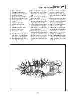
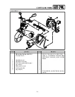
CABLE ROUTING
1
Turn signal relay
2
Main switch assembly
3
Seat lock cable
4
Horn
5
Rectifier / regulator assem-
bly
6
Starter motor negative lead
7
Wire (negative lead)
8
Starter motor positive lead
9
C.D.I. magneto lead
0
C.D.I. unit
q
Pipe 2
w
AI. filter assembly
e
Clamp
r
Vacuum sensing hose
t
Wire harness
y
Side cover (right)
u
Frame Comp.
i
Speedometer cable
o
Front brake hose
p
Throttle cable 1,2
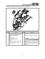
CABLE ROUTING
a
Rear brake cable
s
Speedometer lead
d
Auto choke lead
A
Fasten the wire harness, rear
brake cable and throttle
cable 1,2 to the frame and
cut the end to be shorter than
5mm.
B
Route the front brake hose
through the under fender and
inner fender right side hole.
C
Route the front brake hose
through the front brake hose
holder.
D
Colar white mark to the out-
side.
E
The seat lock cable pass the
frame right side hole into
frame inside, protector part
to the hole position.
F
Clamp the wire harness, wire
positive lead and wire nega-
tive lead to the frame, clamp
position to the white mark
and press to tighten.
G
Fasten the wire harness,
wire positive lead and starter
motor negative lead to the
frame with a plastic locking
tie, point the band tip to for-
ward.
H
Fasten the C.D.I. magneto
lead and wire harness to the
frame with a plastic locking
tie, point the band tip to up-
per and the trunk surface.
I
Secure the ground lead and
the ignition coil base to the
ignition coil stay.
F
4
5
A
F
1
2
3
B
C
D
E
t
F
G
B
B
6
7
8
9
H
I
0
J
q
K
L
M
N
O
w e
r
T
t
o
u
a
p
i
P
u
t
7
6
y
8
7
d
s
Q
FORWARD
BACKWARD
BACKWARD
FORWARD
T
F-F
B-B