


7-35
-
+
ELEC
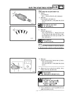
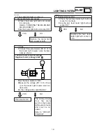
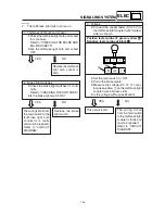
4. Voltage
8
Connect the pocket tester (DC 20 V) to
the horn connector at the pink terminal
as shown.
Positive tester probe
J
J
J
J
J
pink
1
1
1
1
1
Negative tester probe
J
J
J
J
J
ground
8
Set the main switch to “ON”.
8
Measure the voltage (DC 12 V) of pink
1
at the horn terminal.
8
Is the voltage within specification?
YES
NO
1
Br
P
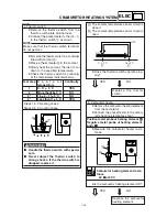
EAS00796
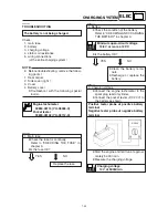
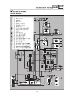
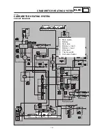
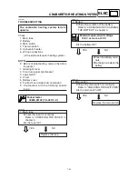
CHECKING THE SIGNALING SYSTEM
1.
The horn fails to sound.
1. Horn switch
8
Check the horn switch for continuity.
Refer to “CHECKING THE SWITCHES”.
8
Is the horn switch OK?
YES
NO
Replace the left
handlebar switch.
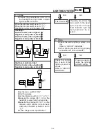
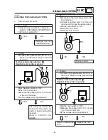
2. Voltage
8
Connect the pocket tester (DC 20 V) to
the horn connector at the horn terminal
as shown.
Positive tester probe
J
J
J
J
J
brown
1
1
1
1
1
Negative tester probe
J
J
J
J
J
ground
8
Set the main switch to “ON”.
8
Push the horn switch.
8
Measure the voltage (DC 12 V) of brown
at the horn terminal.
8
Is the voltage within specification?
YES
NO
The wiring circuit from the
main switch to the horn con-
nector is faulty and must be
repaired.
Refer to “CIRCUIT DIA-
GRAM”.
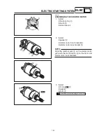
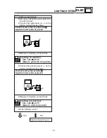
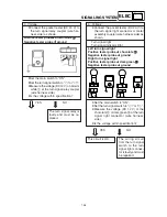
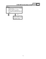
3. Horn
8
Disconnect the pink connector at the
horn terminal.
8
Connect a jumper lead
1
to the horn
terminal and ground the jumper lead.
8
Set the main switch to “ON”.
8
Push the horn switch.
8
Does the horn sound?
NO
YES
The horn is OK.
Replace the horn.
Repair or replace the
horn.
1
Br
P
1
Br
P
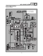
SIGNALING SYSTEM