


7-39
-
+
ELEC
EAS00804
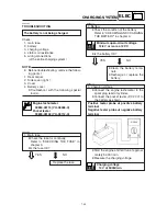
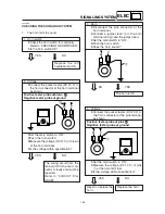
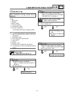
4. The fuel level meter fails to operate.
1. Fuel sender
8
Remove the fuel sender from the fuel
tank.
8
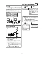
Connect the pocket tester (
Ω
×
1) to the
fuel sender coupler (wire harness side)
as shown.
Positive tester probe
J
J
J
J
J
green
1
1
1
1
1
Negative tester probe
J
J
J
J
J
black
2
2
2
2
2
8
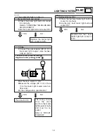
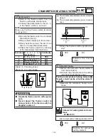
Measure the fuel sender resistances.
Fuel sender resistance (up position
F)(
Ω
Ω
Ω
Ω
Ω
×××××
1)
4~10
Ω
Ω
Ω
Ω
Ω
at 20°C
Fuel sender resistance (down po-
sition E)(
Ω
Ω
Ω
Ω
Ω
×××××
10)
90~100
Ω
Ω
Ω
Ω
Ω
at 20°C
8
Is the fuel sender OK?
YES
NO
Replace the fuel sender.
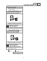
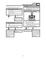
2. Voltage
8
Connect the pocket tester (DC 20 V) to
the meter light coupler (wire harness
side) as shown.
Positive tester probe
J
J
J
J
J
brown
1
1
1
1
1
Negative tester probe
J
J
J
J
J
black
2
2
2
2
2
8
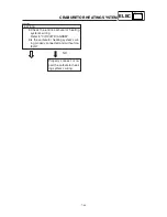
Set the main switch to “ON”.
8
Measure the voltage (DC 12 V) of brown
1
on the meter light coupler (wire har-
ness side).
8
Is the voltage within specification?
YES
NO
Check the wiring connec-
tions of the entire signal-
ing system.
Refer to “CIRCUIT DIA-
GRAM”.
1
(F)
(E)
2
G
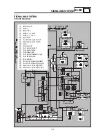
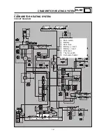
B
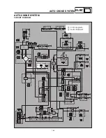
SIGNALING SYSTEM
1
2
L
B
Br
G
Br
G
L
B