


7-38
-
+
ELEC
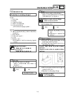
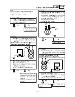
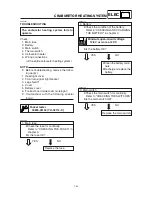
4. Voltage
8
Connect the pocket tester (DC 20 V) to
the turn signal relay coupler (wire har-
ness side) as shown.
Positive tester probe
J
J
J
J
J
brown/white
1
1
1
1
1
Negative tester probe
J
J
J
J
J
ground
8
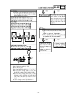
Set the main switch to “ON”.
8
Set the turn signal switch to “
4
” or “
6
”.
8
Measure the voltage (DC 12 V) on brown/
white
1
at the turn signal relay coupler
(wire harness side).
8
Is the voltage within specification?
YES
NO
The turn signal relay is
faulty and must be re-
placed.
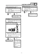
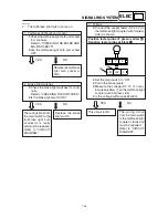
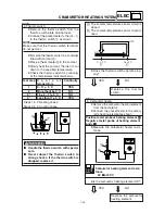
5. Voltage
8
Connect the pocket tester (DC 20 V) to
the turn signal light connector or meter
assembly coupler (wire harness side) as
shown.
Turn signal light
Turn signal indicator light
Left turn signal light
Positive tester probe
J
J
J
J
J
chocolate
1
1
1
1
1
Negative tester probe
J
J
J
J
J
ground
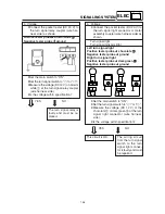
Right turn signal light
Positive tester probe
J
J
J
J
J
dark green
2
2
2
2
2
Negative tester probe
J
J
J
J
J
ground
8
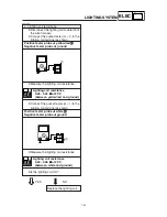
Set the main switch to “ON”.
8
Set the turn signal switch to “
4
” or “
6
”.
8
Measure the voltage (DC 12 V) of the
chocolate
1
or dark green
2
at the turn
signal light connector (wire harness
side).
8
Is the voltage within specification?
YES
NO
The wiring circuit
from the turn signal
switch to the turn
signal light connec-
tor is faulty and must
be repaired.
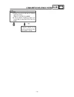
This circuit is OK.
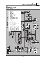
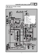
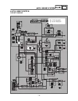
SIGNALING SYSTEM
1
B
Br/W
Br
1
2
Ch B
Ch B
Dg B
Dg B