REAR BRAKE
4-59
• When refilling, be careful that water does
not enter the brake master cylinder reser-
voir. Water will significantly lower the boil-
ing point of the brake fluid and could cause
vapor lock.
NOTICE
ECA13540
Brake fluid may damage painted surfaces
and plastic parts. Therefore, always clean up
any spilt brake fluid immediately.
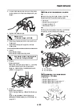
5. Bleed:
• Brake system
Refer to “BLEEDING THE HYDRAULIC
BRAKE SYSTEM (ABS) (for YP125RA)” on
page 3-11.
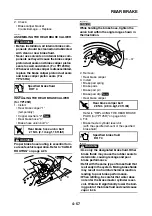
6. Check:
• Brake fluid level
Below the minimum level mark “a”
→
Add the
specified brake fluid to the proper level.
Refer to “CHECKING THE BRAKE FLUID
LEVEL” on page 3-10.
7. Check:
• Brake lever operation
Soft or spongy feeling
→
Bleed the brake sys-
tem.
Refer to “BLEEDING THE HYDRAULIC
BRAKE SYSTEM (ABS) (for YP125RA)” on
page 3-11.
EAS22700
REMOVING THE REAR BRAKE MASTER
CYLINDER
TIP
Before removing the rear brake master cylinder,
drain the brake fluid from the entire brake sys-
tem.
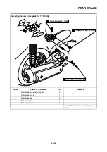
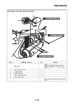
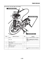
1. Remove:
• Brake hose union bolt “1”
• Copper washers “2”
• Brake hose “3”
TIP
To collect any remaining brake fluid, place a
container under the master cylinder and the end
of the brake hose.
EAS22710
CHECKING THE REAR BRAKE MASTER
CYLINDER
1. Check:
• Brake master cylinder
Damage/scratches/wear
→
Replace.
• Brake fluid delivery passages
(brake master cylinder body)
Obstruction
→
Blow out with compressed air.
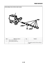
2. Check:
• Brake master cylinder kit
Damage/scratches/wear
→
Replace.
3. Check:
• Brake master cylinder reservoir cap
• Brake master cylinder reservoir diaphragm
holder
• Brake master cylinder reservoir diaphragm
Damage/wear
→
Replace.
4. Check:
• Rear brake hose
Cracks/damage/wear
→
Replace.
EAS22730
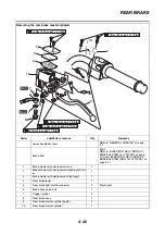
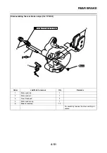
ASSEMBLING THE REAR BRAKE MASTER
CYLINDER
WARNING
EWA13520
• Before installation, all internal brake com-
ponents should be cleaned and lubricated
with clean or new brake fluid.
• Never use solvents on internal brake com-
ponents.
a
Specified brake fluid
DOT 4
1
3
2
Содержание MBK XMAX 2014
Страница 1: ...2014 SERVICE MANUAL YP125R YP125RA 2DM F8197 E0 ...
Страница 6: ......
Страница 8: ......
Страница 64: ...TIGHTENING TORQUES 2 17 Muffler tightening sequence 1 2 3 ...
Страница 72: ...LUBRICATION SYSTEM DIAGRAMS 2 25 EAS2DM1116 LUBRICATION SYSTEM DIAGRAMS 1 2 3 4 5 3 ...
Страница 73: ...LUBRICATION SYSTEM DIAGRAMS 2 26 1 Camshaft 2 Crankshaft 3 Oil pump 4 Oil filter 5 Oil strainer ...
Страница 78: ...CABLE ROUTING 2 31 Steering head front view 1 2 3 4 5 6 8 8 A 7 7 ...
Страница 80: ...CABLE ROUTING 2 33 Front brake left side view for YP125R 1 2 2 1 1 2 2 D E A B C ...
Страница 82: ...CABLE ROUTING 2 35 Front brake left side view for YP125RA 2 1 1 2 1 2 2 A B D E C ...
Страница 84: ...CABLE ROUTING 2 37 Engine and rear brake left side and right side view for YP125R B 2 1 2 1 2 A A 3 3 C ...
Страница 86: ...CABLE ROUTING 2 39 Engine and rear brake left side and right side view for YP125RA 1 2 1 2 2 A A B 3 4 3 4 4 ...
Страница 92: ...CABLE ROUTING 2 45 Frame right side view 3 2 4 1 2 3 A B 6 5 3 A B 3 3 2 3 3 A A B A B B 3 ...
Страница 94: ...CABLE ROUTING 2 47 Engine right side view 6 6 6 6 C D C D D C 10 B 9 5 6 1 2 8 3 4 5 6 7 A ...
Страница 98: ...CABLE ROUTING 2 51 Frame left side view C D C D 2 1 E 1 2 D C 6 1 4 5 3 2 1 7 3 2 1 A B ...
Страница 100: ...CABLE ROUTING 2 53 Engine left side view 1 1 1 1 1 2 3 4 5 6 7 8 9 7 7 A B A B A B 1 ...
Страница 102: ...CABLE ROUTING 2 55 Frame top view 7 8 9 10 11 12 13 13 17 19 19 A D B C 14 C B 1 2 3 4 5 6 14 15 16 18 19 ...
Страница 104: ...CABLE ROUTING 2 57 Engine and frame top view 1 2 4 5 6 7 8 9 10 11 12 13 1 4 5 6 7 8 1 3 10 11 6 8 C 3 11 B A B A 3 ...
Страница 106: ...CABLE ROUTING 2 59 Rear brake right side view 2 2 2 2 2 2 1 1 2 3 A B C 3 ...
Страница 108: ...CABLE ROUTING 2 61 Hydraulic unit for YP125RA 3 2 1 2 3 3 2 2 3 2 2 2 3 3 3 4 4 1 1 4 2 6 B A A 5 1 5 1 5 ...
Страница 110: ...CABLE ROUTING 2 63 ...
Страница 228: ...REAR SHOCK ABSORBER ASSEMBLIES AND SWINGARM 4 89 ...
Страница 231: ......
Страница 291: ...CRANKSHAFT 5 60 a 1 ...
Страница 292: ...CRANKSHAFT 5 61 ...
Страница 302: ...WATER PUMP 6 9 ...
Страница 313: ......
Страница 329: ...CHARGING SYSTEM 8 16 2 AC magneto 3 Rectifier regulator 12 Battery 13 Main fuse 17 Frame ground ...
Страница 331: ...CHARGING SYSTEM 8 18 ...
Страница 349: ...COOLING SYSTEM 8 36 ...
Страница 391: ...FUEL PUMP SYSTEM 8 78 ...
Страница 400: ...IMMOBILIZER SYSTEM 8 87 a Light on b Light off ...
Страница 401: ...IMMOBILIZER SYSTEM 8 88 ...
Страница 405: ...ABS ANTI LOCK BRAKE SYSTEM for YP125RA 8 92 ...
Страница 439: ...ABS ANTI LOCK BRAKE SYSTEM for YP125RA 8 126 ...
Страница 464: ...ELECTRICAL COMPONENTS 8 151 ...
Страница 476: ......
Страница 477: ......
Страница 478: ......

