


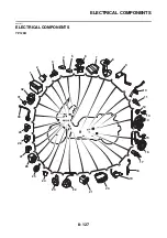


ELECTRICAL COMPONENTS
8-135
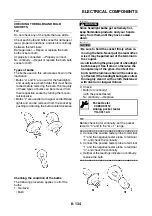
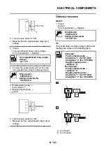
Checking the condition of the bulb sockets
The following procedure applies to all of the bulb
sockets.
1. Check:
• Bulb socket (for continuity)
(with the pocket tester)
No continuity
→
Replace.
TIP
Check each bulb socket for continuity in the
same manner as described in the bulb section,
however, note the following.
▼▼▼
▼
▼ ▼▼▼
▼
▼ ▼▼▼
▼
▼ ▼▼▼
▼
▼ ▼▼▼
▼
▼ ▼▼▼
▼
▼▼▼
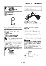
a. Install a good bulb into the bulb socket.
b. Connect the pocket tester probes to the re-
spective leads of the bulb socket.
c. Check the bulb socket for continuity. If any of
the readings indicate no continuity, replace
the bulb socket.
▲▲▲
▲
▲ ▲▲▲
▲
▲ ▲▲▲
▲
▲ ▲▲▲
▲
▲ ▲▲▲
▲
▲ ▲▲▲
▲
▲▲▲
EAS28000
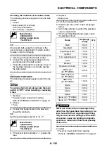
CHECKING THE FUSES
The following procedure applies to all of the fus-
es.
NOTICE
ECA1SD1017
To avoid a short circuit, always turn the main
switch to “OFF” when checking or replacing
a fuse.
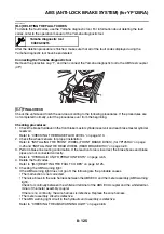
1. Remove:
• Fuse box cover and/or front cowling
Refer to “GENERAL CHASSIS” on page 4-1.
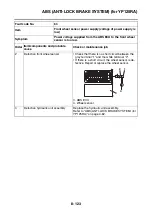
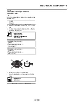
2. Check:
• Fuse
▼▼▼
▼
▼ ▼▼▼
▼
▼ ▼▼▼
▼
▼ ▼▼▼
▼
▼ ▼▼▼
▼
▼ ▼▼▼
▼
▼▼▼
a. Connect the pocket tester to the fuse and
check the continuity.
TIP
Set the pocket tester selector to “
Ω
×
1”.
b. If the pocket tester indicates “
∞
”, replace the
fuse.
▲▲▲
▲
▲ ▲▲▲
▲
▲ ▲▲▲
▲
▲ ▲▲▲
▲
▲ ▲▲▲
▲
▲ ▲▲▲
▲
▲▲▲
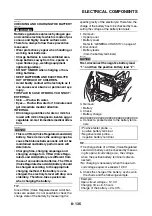
3. Replace:
• Blown fuse
▼▼▼
▼
▼ ▼▼▼
▼
▼ ▼▼▼
▼
▼ ▼▼▼
▼
▼ ▼▼▼
▼
▼ ▼▼▼
▼
▼▼▼
a. Turn the main switch to “OFF”.
b. Install a new fuse of the correct amperage
rating.
c. Set on the switches to verify if the electrical
circuit is operational.
d. If the fuse immediately blows again, check
the electrical circuit.
WARNING
EWA13310
Never use a fuse with an amperage rating
other than that specified. Improvising or us-
ing a fuse with the wrong amperage rating
may cause extensive damage to the electri-
cal system, cause the lighting and ignition
systems to malfunction and could possibly
cause a fire.
▲▲▲
▲
▲ ▲▲▲
▲
▲ ▲▲▲
▲
▲ ▲▲▲
▲
▲ ▲▲▲
▲
▲ ▲▲▲
▲
▲▲▲
4. Install:
• Fuse box cover and/or front cowling
Refer to “GENERAL CHASSIS” on page 4-1.
Pocket tester
90890-03112
Analog pocket tester
YU-03112-C
Pocket tester
90890-03112
Analog pocket tester
YU-03112-C
Fuses
Amperage
rating
Q’ty
Main
30.0 A
1
Headlight
20.0 A
1
Signaling system
10.0 A
1
Ignition
10.0 A
1
Turn signal/hazard
10.0 A
1
ECU
10.0 A
1
Backup
10.0 A
1
Radiator fan motor
7.5 A
1
ABS motor
(for YP125RA)
30.0 A
1
ABS solenoid
(for YP125RA)
20.0 A
1
ABS ECU
(for YP125RA)
10.0 A
1
Spare
30.0 A
1
Spare
20.0 A
1
Spare
10.0 A
1
Spare
7.5 A
1
Spare (for YP125RA)
30.0 A
1
Spare (for YP125RA)
10.0 A
1
Содержание MBK XMAX 2014
Страница 1: ...2014 SERVICE MANUAL YP125R YP125RA 2DM F8197 E0 ...
Страница 6: ......
Страница 8: ......
Страница 64: ...TIGHTENING TORQUES 2 17 Muffler tightening sequence 1 2 3 ...
Страница 72: ...LUBRICATION SYSTEM DIAGRAMS 2 25 EAS2DM1116 LUBRICATION SYSTEM DIAGRAMS 1 2 3 4 5 3 ...
Страница 73: ...LUBRICATION SYSTEM DIAGRAMS 2 26 1 Camshaft 2 Crankshaft 3 Oil pump 4 Oil filter 5 Oil strainer ...
Страница 78: ...CABLE ROUTING 2 31 Steering head front view 1 2 3 4 5 6 8 8 A 7 7 ...
Страница 80: ...CABLE ROUTING 2 33 Front brake left side view for YP125R 1 2 2 1 1 2 2 D E A B C ...
Страница 82: ...CABLE ROUTING 2 35 Front brake left side view for YP125RA 2 1 1 2 1 2 2 A B D E C ...
Страница 84: ...CABLE ROUTING 2 37 Engine and rear brake left side and right side view for YP125R B 2 1 2 1 2 A A 3 3 C ...
Страница 86: ...CABLE ROUTING 2 39 Engine and rear brake left side and right side view for YP125RA 1 2 1 2 2 A A B 3 4 3 4 4 ...
Страница 92: ...CABLE ROUTING 2 45 Frame right side view 3 2 4 1 2 3 A B 6 5 3 A B 3 3 2 3 3 A A B A B B 3 ...
Страница 94: ...CABLE ROUTING 2 47 Engine right side view 6 6 6 6 C D C D D C 10 B 9 5 6 1 2 8 3 4 5 6 7 A ...
Страница 98: ...CABLE ROUTING 2 51 Frame left side view C D C D 2 1 E 1 2 D C 6 1 4 5 3 2 1 7 3 2 1 A B ...
Страница 100: ...CABLE ROUTING 2 53 Engine left side view 1 1 1 1 1 2 3 4 5 6 7 8 9 7 7 A B A B A B 1 ...
Страница 102: ...CABLE ROUTING 2 55 Frame top view 7 8 9 10 11 12 13 13 17 19 19 A D B C 14 C B 1 2 3 4 5 6 14 15 16 18 19 ...
Страница 104: ...CABLE ROUTING 2 57 Engine and frame top view 1 2 4 5 6 7 8 9 10 11 12 13 1 4 5 6 7 8 1 3 10 11 6 8 C 3 11 B A B A 3 ...
Страница 106: ...CABLE ROUTING 2 59 Rear brake right side view 2 2 2 2 2 2 1 1 2 3 A B C 3 ...
Страница 108: ...CABLE ROUTING 2 61 Hydraulic unit for YP125RA 3 2 1 2 3 3 2 2 3 2 2 2 3 3 3 4 4 1 1 4 2 6 B A A 5 1 5 1 5 ...
Страница 110: ...CABLE ROUTING 2 63 ...
Страница 228: ...REAR SHOCK ABSORBER ASSEMBLIES AND SWINGARM 4 89 ...
Страница 231: ......
Страница 291: ...CRANKSHAFT 5 60 a 1 ...
Страница 292: ...CRANKSHAFT 5 61 ...
Страница 302: ...WATER PUMP 6 9 ...
Страница 313: ......
Страница 329: ...CHARGING SYSTEM 8 16 2 AC magneto 3 Rectifier regulator 12 Battery 13 Main fuse 17 Frame ground ...
Страница 331: ...CHARGING SYSTEM 8 18 ...
Страница 349: ...COOLING SYSTEM 8 36 ...
Страница 391: ...FUEL PUMP SYSTEM 8 78 ...
Страница 400: ...IMMOBILIZER SYSTEM 8 87 a Light on b Light off ...
Страница 401: ...IMMOBILIZER SYSTEM 8 88 ...
Страница 405: ...ABS ANTI LOCK BRAKE SYSTEM for YP125RA 8 92 ...
Страница 439: ...ABS ANTI LOCK BRAKE SYSTEM for YP125RA 8 126 ...
Страница 464: ...ELECTRICAL COMPONENTS 8 151 ...
Страница 476: ......
Страница 477: ......
Страница 478: ......