


ABS (ANTI-LOCK BRAKE SYSTEM) (for YP125RA)
4-66
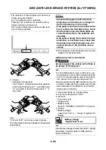
• The operation of the hydraulic unit can be con-
firmed using the indicator.
On: The hydraulic unit is operating.
Flashing: The conditions for operating the hy-
draulic unit have not been met.
Off: The front brake lever and rear brake lever
are not being operated.
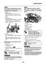
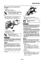
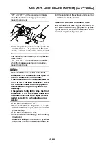
9. Check:
• Hydraulic unit operation
Click “Action”, a single pulse will be generat-
ed in the front brake lever “1”, rear brake lever
“2”, and again in the front brake lever “1”, in
this order.
TIP
“ON” and “OFF” on the tool screen indicate
when the brakes are being applied and released
respectively.
NOTICE
ECA2DM1043
• Check that the pulse is felt in the front
brake lever, rear brake lever, and again in
the front brake lever, in this order.
• If the pulse is felt in the rear brake lever be-
fore it is felt in the front brake lever, check
that the brake hoses and brake pipes are
connected correctly to the hydraulic unit
assembly.
• If the pulse is hardly felt in either the front
brake lever or rear brake lever, check that
the brake hoses and brake pipes are con-
nected correctly to the hydraulic unit as-
sembly.
10.If the operation of the hydraulic unit is normal,
delete all of the fault codes.
ABS reaction-force confirmation
WARNING
EWA13120
Securely support the vehicle so that there is
no danger of it falling over.
TIP
• For the ABS reaction-force confirmation, use
the diagnosis mode of the Yamaha diagnostic
tool. For more information, refer to the opera-
tion manual of the Yamaha diagnostic tool.
• Before performing the ABS reaction-force con-
firmation, make sure that no malfunctions have
been detected in the ABS ECU and that the
wheels are not rotating.
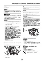
1. Place the vehicle on a center stand.
2. Turn the main switch to “OFF”.
3. Remove:
• Fuse box cover
• Upper panel
• Battery cover
Refer to “GENERAL CHASSIS” on page 4-1.
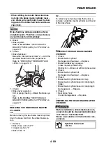
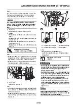
4. Check:
• Battery voltage
Lower than 12.8 V
→
Charge or replace the
battery.
TIP
If the battery voltage is lower than 12.8 V, charge
the battery, and then perform ABS reaction-
force confirmation.
1
3
2
2
1
Battery voltage
Higher than 12.8 V
Содержание MBK XMAX 2014
Страница 1: ...2014 SERVICE MANUAL YP125R YP125RA 2DM F8197 E0 ...
Страница 6: ......
Страница 8: ......
Страница 64: ...TIGHTENING TORQUES 2 17 Muffler tightening sequence 1 2 3 ...
Страница 72: ...LUBRICATION SYSTEM DIAGRAMS 2 25 EAS2DM1116 LUBRICATION SYSTEM DIAGRAMS 1 2 3 4 5 3 ...
Страница 73: ...LUBRICATION SYSTEM DIAGRAMS 2 26 1 Camshaft 2 Crankshaft 3 Oil pump 4 Oil filter 5 Oil strainer ...
Страница 78: ...CABLE ROUTING 2 31 Steering head front view 1 2 3 4 5 6 8 8 A 7 7 ...
Страница 80: ...CABLE ROUTING 2 33 Front brake left side view for YP125R 1 2 2 1 1 2 2 D E A B C ...
Страница 82: ...CABLE ROUTING 2 35 Front brake left side view for YP125RA 2 1 1 2 1 2 2 A B D E C ...
Страница 84: ...CABLE ROUTING 2 37 Engine and rear brake left side and right side view for YP125R B 2 1 2 1 2 A A 3 3 C ...
Страница 86: ...CABLE ROUTING 2 39 Engine and rear brake left side and right side view for YP125RA 1 2 1 2 2 A A B 3 4 3 4 4 ...
Страница 92: ...CABLE ROUTING 2 45 Frame right side view 3 2 4 1 2 3 A B 6 5 3 A B 3 3 2 3 3 A A B A B B 3 ...
Страница 94: ...CABLE ROUTING 2 47 Engine right side view 6 6 6 6 C D C D D C 10 B 9 5 6 1 2 8 3 4 5 6 7 A ...
Страница 98: ...CABLE ROUTING 2 51 Frame left side view C D C D 2 1 E 1 2 D C 6 1 4 5 3 2 1 7 3 2 1 A B ...
Страница 100: ...CABLE ROUTING 2 53 Engine left side view 1 1 1 1 1 2 3 4 5 6 7 8 9 7 7 A B A B A B 1 ...
Страница 102: ...CABLE ROUTING 2 55 Frame top view 7 8 9 10 11 12 13 13 17 19 19 A D B C 14 C B 1 2 3 4 5 6 14 15 16 18 19 ...
Страница 104: ...CABLE ROUTING 2 57 Engine and frame top view 1 2 4 5 6 7 8 9 10 11 12 13 1 4 5 6 7 8 1 3 10 11 6 8 C 3 11 B A B A 3 ...
Страница 106: ...CABLE ROUTING 2 59 Rear brake right side view 2 2 2 2 2 2 1 1 2 3 A B C 3 ...
Страница 108: ...CABLE ROUTING 2 61 Hydraulic unit for YP125RA 3 2 1 2 3 3 2 2 3 2 2 2 3 3 3 4 4 1 1 4 2 6 B A A 5 1 5 1 5 ...
Страница 110: ...CABLE ROUTING 2 63 ...
Страница 228: ...REAR SHOCK ABSORBER ASSEMBLIES AND SWINGARM 4 89 ...
Страница 231: ......
Страница 291: ...CRANKSHAFT 5 60 a 1 ...
Страница 292: ...CRANKSHAFT 5 61 ...
Страница 302: ...WATER PUMP 6 9 ...
Страница 313: ......
Страница 329: ...CHARGING SYSTEM 8 16 2 AC magneto 3 Rectifier regulator 12 Battery 13 Main fuse 17 Frame ground ...
Страница 331: ...CHARGING SYSTEM 8 18 ...
Страница 349: ...COOLING SYSTEM 8 36 ...
Страница 391: ...FUEL PUMP SYSTEM 8 78 ...
Страница 400: ...IMMOBILIZER SYSTEM 8 87 a Light on b Light off ...
Страница 401: ...IMMOBILIZER SYSTEM 8 88 ...
Страница 405: ...ABS ANTI LOCK BRAKE SYSTEM for YP125RA 8 92 ...
Страница 439: ...ABS ANTI LOCK BRAKE SYSTEM for YP125RA 8 126 ...
Страница 464: ...ELECTRICAL COMPONENTS 8 151 ...
Страница 476: ......
Страница 477: ......
Страница 478: ......