ABS (ANTI-LOCK BRAKE SYSTEM) (for YP125RA)
8-102
6. Condition
The current conditions are displayed. (Detected/Recovered)
7. Symptom
The symptoms of the detected malfunction are displayed.
8. Diagnosis code
The diagnosis codes related to the detected malfunction are displayed.
Fault code table
The details of the fault codes displayed using the Yamaha diagnostic tool are shown in the following
table. Refer to this table when checking the vehicle.
Delete the fault codes when the service is finished. [B-3]
TIP
• Before inspecting the check points, terminate the communication between the Yamaha diagnostic
tool and the vehicle, and then turn the main switch to “OFF”.
• Record all of the fault codes displayed and inspect the check points.
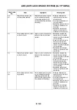
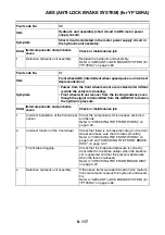
Fault code
No.
Item
Symptom
Check point
11*
25*
Front wheel sensor (inter-
mittent pulses or no puls-
es)
Front wheel sensor signal
is not received properly.
(Pulses are not received
or are received intermit-
tently while the vehicle is
traveling.)
• Foreign material ad-
hered around the front
wheel sensor
• Incorrect installation of
the front wheel
• Defective sensor rotor or
incorrect installation of
the rotor
• Defective front wheel
sensor or incorrect in-
stallation of the sensor
12
Rear wheel sensor (inter-
mittent pulses or no puls-
es)
Rear wheel sensor signal
is not received properly.
(Pulses are not received
or are received intermit-
tently while the vehicle is
traveling.)
• Foreign material ad-
hered around the rear
wheel sensor
• Incorrect installation of
the rear wheel
• Defective sensor rotor or
incorrect installation of
the rotor
• Defective rear wheel
sensor or incorrect in-
stallation of the sensor
13*
26*
Front wheel sensor (ab-
normal pulse period)
Front wheel sensor signal
is not received properly.
(The pulse period is ab-
normal while the vehicle is
traveling.)
• Foreign material ad-
hered around the front
wheel sensor
• Incorrect installation of
the front wheel
• Defective sensor rotor or
incorrect installation of
the rotor
• Defective front wheel
sensor or incorrect in-
stallation of the sensor
Содержание MBK XMAX 2014
Страница 1: ...2014 SERVICE MANUAL YP125R YP125RA 2DM F8197 E0 ...
Страница 6: ......
Страница 8: ......
Страница 64: ...TIGHTENING TORQUES 2 17 Muffler tightening sequence 1 2 3 ...
Страница 72: ...LUBRICATION SYSTEM DIAGRAMS 2 25 EAS2DM1116 LUBRICATION SYSTEM DIAGRAMS 1 2 3 4 5 3 ...
Страница 73: ...LUBRICATION SYSTEM DIAGRAMS 2 26 1 Camshaft 2 Crankshaft 3 Oil pump 4 Oil filter 5 Oil strainer ...
Страница 78: ...CABLE ROUTING 2 31 Steering head front view 1 2 3 4 5 6 8 8 A 7 7 ...
Страница 80: ...CABLE ROUTING 2 33 Front brake left side view for YP125R 1 2 2 1 1 2 2 D E A B C ...
Страница 82: ...CABLE ROUTING 2 35 Front brake left side view for YP125RA 2 1 1 2 1 2 2 A B D E C ...
Страница 84: ...CABLE ROUTING 2 37 Engine and rear brake left side and right side view for YP125R B 2 1 2 1 2 A A 3 3 C ...
Страница 86: ...CABLE ROUTING 2 39 Engine and rear brake left side and right side view for YP125RA 1 2 1 2 2 A A B 3 4 3 4 4 ...
Страница 92: ...CABLE ROUTING 2 45 Frame right side view 3 2 4 1 2 3 A B 6 5 3 A B 3 3 2 3 3 A A B A B B 3 ...
Страница 94: ...CABLE ROUTING 2 47 Engine right side view 6 6 6 6 C D C D D C 10 B 9 5 6 1 2 8 3 4 5 6 7 A ...
Страница 98: ...CABLE ROUTING 2 51 Frame left side view C D C D 2 1 E 1 2 D C 6 1 4 5 3 2 1 7 3 2 1 A B ...
Страница 100: ...CABLE ROUTING 2 53 Engine left side view 1 1 1 1 1 2 3 4 5 6 7 8 9 7 7 A B A B A B 1 ...
Страница 102: ...CABLE ROUTING 2 55 Frame top view 7 8 9 10 11 12 13 13 17 19 19 A D B C 14 C B 1 2 3 4 5 6 14 15 16 18 19 ...
Страница 104: ...CABLE ROUTING 2 57 Engine and frame top view 1 2 4 5 6 7 8 9 10 11 12 13 1 4 5 6 7 8 1 3 10 11 6 8 C 3 11 B A B A 3 ...
Страница 106: ...CABLE ROUTING 2 59 Rear brake right side view 2 2 2 2 2 2 1 1 2 3 A B C 3 ...
Страница 108: ...CABLE ROUTING 2 61 Hydraulic unit for YP125RA 3 2 1 2 3 3 2 2 3 2 2 2 3 3 3 4 4 1 1 4 2 6 B A A 5 1 5 1 5 ...
Страница 110: ...CABLE ROUTING 2 63 ...
Страница 228: ...REAR SHOCK ABSORBER ASSEMBLIES AND SWINGARM 4 89 ...
Страница 231: ......
Страница 291: ...CRANKSHAFT 5 60 a 1 ...
Страница 292: ...CRANKSHAFT 5 61 ...
Страница 302: ...WATER PUMP 6 9 ...
Страница 313: ......
Страница 329: ...CHARGING SYSTEM 8 16 2 AC magneto 3 Rectifier regulator 12 Battery 13 Main fuse 17 Frame ground ...
Страница 331: ...CHARGING SYSTEM 8 18 ...
Страница 349: ...COOLING SYSTEM 8 36 ...
Страница 391: ...FUEL PUMP SYSTEM 8 78 ...
Страница 400: ...IMMOBILIZER SYSTEM 8 87 a Light on b Light off ...
Страница 401: ...IMMOBILIZER SYSTEM 8 88 ...
Страница 405: ...ABS ANTI LOCK BRAKE SYSTEM for YP125RA 8 92 ...
Страница 439: ...ABS ANTI LOCK BRAKE SYSTEM for YP125RA 8 126 ...
Страница 464: ...ELECTRICAL COMPONENTS 8 151 ...
Страница 476: ......
Страница 477: ......
Страница 478: ......


