


ABS (ANTI-LOCK BRAKE SYSTEM) (for YP125RA)
4-64
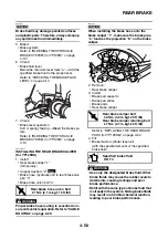
TIP
Do not allow any foreign materials to enter the
hydraulic unit assembly or the brake hoses
when installing the hydraulic unit assembly.
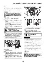
NOTICE
ECA2DM1015
Do not remove the rubber plugs or bolts
(M10
×
1.25) installed in the flare nut holes
before installing the hydraulic unit assem-
bly.
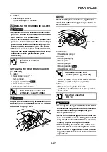
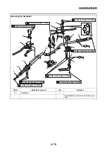
2. Remove:
• Rubber plugs or bolts (M10
×
1.25)
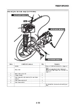
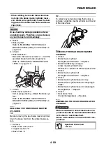
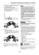
3. Install:
• Brake hose (hydraulic unit to rear brake cali-
per) “1”
• Brake hose (rear brake master cylinder to hy-
draulic unit) “2”
• Brake hose (front brake master cylinder to
hydraulic unit) “3”
• Brake hose (hydraulic unit to front brake cali-
per) “4”
TIP
• Make sure that the crimped section “a” of each
brake hose contacts the hydraulic unit assem-
bly bracket “5” as shown in the illustration.
• Make sure to leave space between the brake
hoses as shown in the illustration.
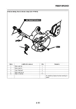
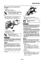
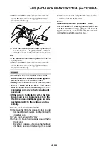
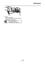
4. Connect:
• ABS ECU coupler “1”
TIP
• Connect the ABS ECU coupler, and then push
the lock lever “a” of the coupler in the direction
of the arrow shown.
• Make sure that the ABS ECU coupler is con-
nected in the correct position as shown in illus-
tration “A”.
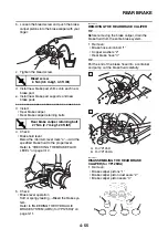
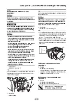
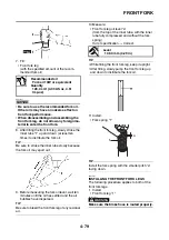
5. Fill:
• Brake master cylinder reservoir
(with the specified amount of the specified
brake fluid)
WARNING
EWA2DM1002
• Use only the designated brake fluid. Other
brake fluids may cause the rubber seals to
deteriorate, causing leakage and poor
brake performance.
• Refill with the same type of brake fluid that
is already in the system. Mixing brake fluids
may result in a harmful chemical reaction,
leading to poor brake performance.
• When refilling, be careful that water does
not enter the brake master cylinder reser-
voir. Water will significantly lower the boil-
ing point of the brake fluid and could cause
vapor lock.
NOTICE
ECA13540
Brake fluid may damage painted surfaces
and plastic parts. Therefore, always clean up
any spilt brake fluid immediately.
T
R
.
.
Brake hose union bolt
30 Nm (3.0 m·kgf, 22 ft·lbf)
4
5
3
2
1
a
A. The ABS ECU coupler is connected correctly.
B. The ABS ECU coupler is not connected.
Specified brake fluid
DOT 4
a
1
A
B
Содержание MBK XMAX 2014
Страница 1: ...2014 SERVICE MANUAL YP125R YP125RA 2DM F8197 E0 ...
Страница 6: ......
Страница 8: ......
Страница 64: ...TIGHTENING TORQUES 2 17 Muffler tightening sequence 1 2 3 ...
Страница 72: ...LUBRICATION SYSTEM DIAGRAMS 2 25 EAS2DM1116 LUBRICATION SYSTEM DIAGRAMS 1 2 3 4 5 3 ...
Страница 73: ...LUBRICATION SYSTEM DIAGRAMS 2 26 1 Camshaft 2 Crankshaft 3 Oil pump 4 Oil filter 5 Oil strainer ...
Страница 78: ...CABLE ROUTING 2 31 Steering head front view 1 2 3 4 5 6 8 8 A 7 7 ...
Страница 80: ...CABLE ROUTING 2 33 Front brake left side view for YP125R 1 2 2 1 1 2 2 D E A B C ...
Страница 82: ...CABLE ROUTING 2 35 Front brake left side view for YP125RA 2 1 1 2 1 2 2 A B D E C ...
Страница 84: ...CABLE ROUTING 2 37 Engine and rear brake left side and right side view for YP125R B 2 1 2 1 2 A A 3 3 C ...
Страница 86: ...CABLE ROUTING 2 39 Engine and rear brake left side and right side view for YP125RA 1 2 1 2 2 A A B 3 4 3 4 4 ...
Страница 92: ...CABLE ROUTING 2 45 Frame right side view 3 2 4 1 2 3 A B 6 5 3 A B 3 3 2 3 3 A A B A B B 3 ...
Страница 94: ...CABLE ROUTING 2 47 Engine right side view 6 6 6 6 C D C D D C 10 B 9 5 6 1 2 8 3 4 5 6 7 A ...
Страница 98: ...CABLE ROUTING 2 51 Frame left side view C D C D 2 1 E 1 2 D C 6 1 4 5 3 2 1 7 3 2 1 A B ...
Страница 100: ...CABLE ROUTING 2 53 Engine left side view 1 1 1 1 1 2 3 4 5 6 7 8 9 7 7 A B A B A B 1 ...
Страница 102: ...CABLE ROUTING 2 55 Frame top view 7 8 9 10 11 12 13 13 17 19 19 A D B C 14 C B 1 2 3 4 5 6 14 15 16 18 19 ...
Страница 104: ...CABLE ROUTING 2 57 Engine and frame top view 1 2 4 5 6 7 8 9 10 11 12 13 1 4 5 6 7 8 1 3 10 11 6 8 C 3 11 B A B A 3 ...
Страница 106: ...CABLE ROUTING 2 59 Rear brake right side view 2 2 2 2 2 2 1 1 2 3 A B C 3 ...
Страница 108: ...CABLE ROUTING 2 61 Hydraulic unit for YP125RA 3 2 1 2 3 3 2 2 3 2 2 2 3 3 3 4 4 1 1 4 2 6 B A A 5 1 5 1 5 ...
Страница 110: ...CABLE ROUTING 2 63 ...
Страница 228: ...REAR SHOCK ABSORBER ASSEMBLIES AND SWINGARM 4 89 ...
Страница 231: ......
Страница 291: ...CRANKSHAFT 5 60 a 1 ...
Страница 292: ...CRANKSHAFT 5 61 ...
Страница 302: ...WATER PUMP 6 9 ...
Страница 313: ......
Страница 329: ...CHARGING SYSTEM 8 16 2 AC magneto 3 Rectifier regulator 12 Battery 13 Main fuse 17 Frame ground ...
Страница 331: ...CHARGING SYSTEM 8 18 ...
Страница 349: ...COOLING SYSTEM 8 36 ...
Страница 391: ...FUEL PUMP SYSTEM 8 78 ...
Страница 400: ...IMMOBILIZER SYSTEM 8 87 a Light on b Light off ...
Страница 401: ...IMMOBILIZER SYSTEM 8 88 ...
Страница 405: ...ABS ANTI LOCK BRAKE SYSTEM for YP125RA 8 92 ...
Страница 439: ...ABS ANTI LOCK BRAKE SYSTEM for YP125RA 8 126 ...
Страница 464: ...ELECTRICAL COMPONENTS 8 151 ...
Страница 476: ......
Страница 477: ......
Страница 478: ......