– 68 –
CHAS
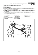
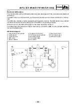
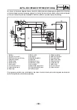
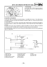
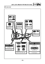
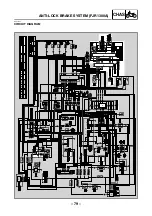
As shown in the block diagram below, the ECU (ABS) receives wheel sensor signals from the front
and rear wheels and also receives signals from other monitor circuits. Both a main microcomputer
and a sub microcomputer are installed in the ECU (ABS) to provide mutual monitoring.
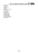
1
Battery
2
Engine stop switch
3
Starting circuit cut-off relay
4
Sidestand switch
5
Starter relay
6
Starter motor
7
Start switch
8
Front wheel sensor
9
Rear wheel sensor
0
Main fuse
A
Main switch
B
Generator
C
Rectifier/regulator
D
ABS fuse
E
ABS motor fuse
F
ABS test coupler
G
ECU (ABS)
H
Rear brake light switch
I
Front brake light switch
J
Tail/brake light
K
Meter assembly
L
ABS warning light
M
Fail-safe relay
N
ABS motor relay
O
Solenoid relay
P
Hydraulic unit
Q
ABS motor
R
Front solenoid
S
Rear solenoid
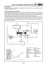
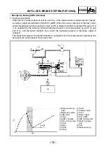
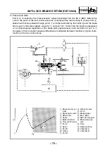
The necessary actions are confirmed by the motor monitor circuit and control signals are transmit-
ted to the hydraulic unit and fail-safe relay.
N
O
P
Q
R
S
H
I
J
K
1
=
A
B C
D
E
F
2
3
4
5
6
7
8
9
G
L
M
ANTI-LOCK BRAKE SYSTEM (FJR1300A)
Содержание 2003 FJR1300
Страница 1: ...2003 FJR1300 R FJR1300A R 5JW1 AE4 SUPPLEMENTARY SERVICE MANUAL ...
Страница 2: ......
Страница 61: ... 53 CHAS INSTALLING THE BEARING 1 Install bearing 1 a 3 5 4 5 mm b rear wheel a b 1 REAR WHEEL AND BRAKE DISC ...
Страница 159: ......
Страница 160: ...YAMAHA MOTOR CO LTD 2500 SHINGAI IWATA SHIZUOKA JAPAN ...

