– 92 –
CHAS
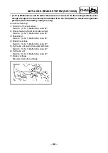
• [C-5-3] Malfunction codes 13 (front wheel) and 14 (rear wheel) (Incorrect signal is detected
from either the front or rear wheel.)
1) The wheel sensors or sensor rotors are not properly installed.
1
Installation of the front or rear wheel sensor
• Check that the wheel sensor is properly installed in the housing.
→
[D-3, 4]
• Check if there is looseness between the housing and the wheel.
→
[D-3, 4]
2
Installation of the front or rear wheel sensor rotor
• Check that the sensor rotor is correctly pressed in the wheel.
→
[D-3, 4]
• Check the rotor and inside the rotor housing for foreign materials.
→
[D-3, 4]
2) Teeth surfaces of the sensor rotors are defective.
• Check for flaws on the teeth surfaces of the front or rear wheel sensor rotors.
Also, check for any foreign materials.
→
[D-3, 4]
3) Sensor output has dropped.
• Sensor signal output may drop due to failure of the bearings, wheel axle, wheel or sensor hous-
ing of the front or rear wheel. Check these components when installed for looseness, distortion,
and bends.
• [C-5-4] Malfunction codes 15 (front wheel sensor) and 16 (rear wheel sensor) (No continuity
in the sensor circuits.)
Broken front or rear wheel sensor circuit is detected.
• Front or rear wheel sensor coupler is broken.
→
[D-3, 4]
• Front or rear wheel sensor or lead is broken.
→
[D-3, 4]
• Sub-wire harness (ABS) sensor circuit is broken.
→
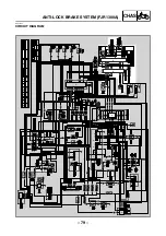
(Refer to “CIRCUIT DIAGRAM”.)
• Sub-wire harness (ABS) is disconnected from the ECU (ABS) coupler terminal.
→
[D-1]
NOTE:
_
• Check that both the front and rear wheel sensor couplers are connected securely.
• If the motorcycle is ridden after malfunction code 15 (front wheel sensor) or 16 (rear wheel sensor)
is displayed, the malfunction code will be overwritten from 15 to 11 (front wheel sensor signal) or
from 16 to 12 (rear wheel sensor signal).
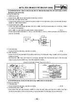
• [C-5-5] Malfunction code 21 (Hydraulic unit solenoid circuit is broken or short-circuited.)
Check the following:
1) Hydraulic unit solenoid coupler
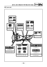
• Check if the hydraulic unit solenoid coupler terminal is disconnected. (Refer to “ABS COU-
PLERS”.)
2) Hydraulic unit solenoid
• Check the front and rear wheel solenoids for continuity
→
[D-5]
• Check the insulation of all solenoid terminals and the negative battery terminal.
→
[D-5]
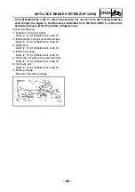
3) Sub-wire harness (ABS)
• Check the hydraulic unit solenoid circuits for continuity. (See the illustration below.)
• Check the insulation of the hydraulic unit solenoid circuits and the negative battery terminal.
Fail-safe
relay
ECU (ABS)
Front
solenoid
Rear
solenoid
Continuity
between:
red
green
white
red
red
ANTI-LOCK BRAKE SYSTEM (FJR1300A)
Содержание 2003 FJR1300
Страница 1: ...2003 FJR1300 R FJR1300A R 5JW1 AE4 SUPPLEMENTARY SERVICE MANUAL ...
Страница 2: ......
Страница 61: ... 53 CHAS INSTALLING THE BEARING 1 Install bearing 1 a 3 5 4 5 mm b rear wheel a b 1 REAR WHEEL AND BRAKE DISC ...
Страница 159: ......
Страница 160: ...YAMAHA MOTOR CO LTD 2500 SHINGAI IWATA SHIZUOKA JAPAN ...

