– 84 –
CHAS
EAS00887
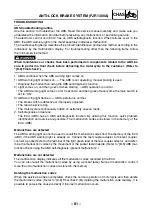
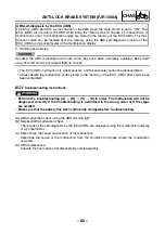
ABS troubleshooting
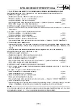
• [A] ABS malfunction check using the ABS warning light
Set the main switch to “ON”. (Do not start the engine.)
1) Warning light does not come on.
→
[B-1]
2) Warning light remains on.
→
[B-2]
3) Warning light flashes.
→
[B-3]
4) Warning light comes on for 2 seconds, then goes off.
→
[B-4]
• [B] Detailed ABS malfunction check
• [B-1] Warning light does not come on
Do other indicators operate normally?
1) Yes.
→
[C-1]
2) No.
→
[C-2]
• [B-2] ABS warning light remains on
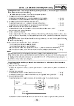
Check the ECU (ABS) under the tray. Is the coupler connected securely?
1) Yes.
→
[B-5]
2) No.
→
Connect the coupler securely until a “click” sound is heard.
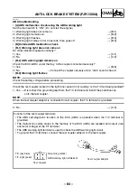
• [B-3] Warning light flashes
NOTE:
_
Check the battery voltage before proceeding.
Check the test coupler located in the right inner panel (front cowling). Is the T/C terminal grounded?
1) Yes.
→
Disconnect the grounding lead from the T/C terminal and install the protective cap
onto the test coupler.
NOTE:
_
When the test coupler adaptor is connected to test coupler, the T/C terminal is grounded.
2) No.
→
[C-3]
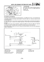
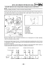
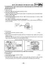
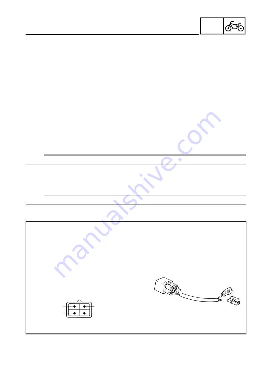
Function of the test coupler terminals
• The ABS self-diagnostic function of the ECU (ABS) is operated when the T/C terminal is
grounded.
• The malfunction codes stored in the memory of the ECU (ABS) are recalled and output (rise
and fall of voltage) at the T/F terminal.
• The ABS warning light terminal is used to check the ABS warning light circuit.
• To ground the T/C terminal, connect the test coupler adaptor to the test coupler.
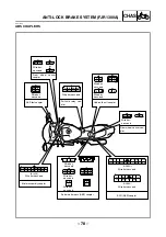
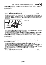
T/C (sky blue)
T/F (light green)
Grounding (black)
ABS warning light (white/red)
Test coupler adaptor
Test coupler
ANTI-LOCK BRAKE SYSTEM (FJR1300A)
Содержание 2003 FJR1300
Страница 1: ...2003 FJR1300 R FJR1300A R 5JW1 AE4 SUPPLEMENTARY SERVICE MANUAL ...
Страница 2: ......
Страница 61: ... 53 CHAS INSTALLING THE BEARING 1 Install bearing 1 a 3 5 4 5 mm b rear wheel a b 1 REAR WHEEL AND BRAKE DISC ...
Страница 159: ......
Страница 160: ...YAMAHA MOTOR CO LTD 2500 SHINGAI IWATA SHIZUOKA JAPAN ...

