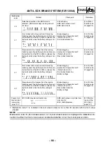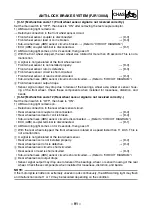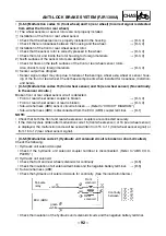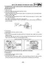
– 103 –
CHAS
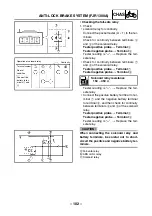
2. Check:
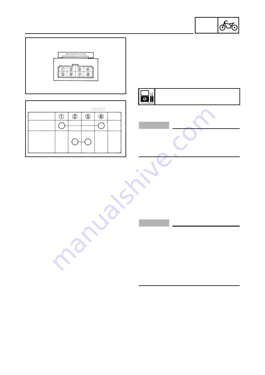
• ABS motor relay for continuity
Connect the pocket tester (
Ω
×
1) to the ter-
minals of the ABS motor relay.
Check for continuity between terminals
1
and
6
of the ABS motor relay.
Tester positive probe
→
Terminal
1
Tester negative probe
→
Terminal
6
Tester reading is “
∞
”.
→
Replace the fail-
safe relay.
CAUTION:
_
Do not reverse the connections. If the
pocket tester leads are connected in
reverse to terminals
1
and
6
, a correct
pocket tester reading cannot be obtained.
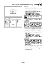
• Connect the positive battery terminal to ter-
minal
6
and the negative battery terminal
to terminal
1
, and then check for continuity
between terminals
2
and
5
of the ABS
motor relay.
Tester positive probe
→
Terminal
2
Tester negative probe
→
Terminal
5
Tester reading is “
∞
”.
→
Replace the fail-
safe relay.
CAUTION:
_
• Be sure to connect the pocket tester posi-
tive and negative probes correctly. If the
pocket tester probes are connected in
reverse, the diode of the fail-safe relay
will be broken.
• When connecting the battery and the ABS
motor relay terminals, be careful not to
short-circuit the positive and negative
battery terminals.
ABS motor relay resistance
50 ~ 150
Ω
Operation of ABS motor relay
Terminal number
Continuity
Normal
condition
Connect the
battery to ter-
minals
6
and
1
ANTI-LOCK BRAKE SYSTEM (FJR1300A)
Содержание 2003 FJR1300
Страница 1: ...2003 FJR1300 R FJR1300A R 5JW1 AE4 SUPPLEMENTARY SERVICE MANUAL ...
Страница 2: ......
Страница 61: ... 53 CHAS INSTALLING THE BEARING 1 Install bearing 1 a 3 5 4 5 mm b rear wheel a b 1 REAR WHEEL AND BRAKE DISC ...
Страница 159: ......
Страница 160: ...YAMAHA MOTOR CO LTD 2500 SHINGAI IWATA SHIZUOKA JAPAN ...


