


www.xpand.me 15 www.xpandvision.com
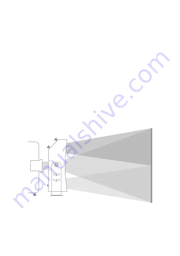
Upper Half Image
Digital Projector
Bottom Half Image
Central Image
the router’s user manual for more information). However, depending on your network’s confi guration, IP address reservation
may need to be done elsewhere on the network.
7. After step 5, the PC-based Confi guration Utility should still be connected to the Trinity Polarizer unit and its IP address can now be
updated with that acquired in step 6. To do so press the “Change Network Settings on Device” button. This enables changing of network
settings on the connected device, including its IP address. Enter the new IP address from step 6 in the “Device IP” fi eld. If the unit and
the device which will be controlling it are on the same subnetwork then the network mask should be set to 255.255.255.0 and the
default gateway setting is not critical. However if they are on different subnetworks, the mask and default gateway should be confi gured
properly based on your network’s structure. Consult your IT department for help.
8.
Remember the new IP which you entered!
To send it and other network settings to the device press the “Confi rm New Network
Settings” button.
Warning! If you assign an invalid address to the unit you will no longer be able to access it over the network!
You will be able to access it again by connecting it directly to your PC as described in step 5b) if setting the PC’s static address
so that the fi rst three numbers are the same as those of the unit’s IP which you have just set. So if you set the IP address
to 1.2.3.4 you will only be able to access it directly from your PC as described in 5b), if setting the PC’s static IP address to
1.2.3.* (excluding 1.2.3.4).
9. Since the unit’s IP has now been changed a new device must be added to the list of known devices inside the confi guration utility. Click
the “Add new device” link and enter a device name, its new IP and make sure the port is set to 1000. An attempt to connect to this device
will then be made. If you were confi guring the unit by direct connection with a crossover cable this attempt will fail and you have to
connect the Trinity unit and the PC to their respective networks (make sure to fi rst reset you PC network settings you may have changed
in step 5b). If an automatic connection attempt is not made by the utility, initiate it manually by clicking the “Get Device State” button.
Once a successful connection is made, device information read from the unit will be updated in appropriate fi elds of the confi guration utility.
Note:
The network may require some time to refresh its list of known devices and accept the new IP address for the unit. If reconnection
fails, try waiting a minute or two before trying again. You can also disconnect the device from the network during that time.
Adjusting the Image Position
Internal workings of the Trinity Polarizer are such, that the incoming image from the projector is split into three separate images which are
then reunited on the screen. One of the three images is a 3D image for one eye - central image. The 3D image for the other eye is split
horizontally into an upper and bottom half image. On the screen the two halves need to be aligned to each other as well as to the central
image.
Figure 7
shows the concept just described. Note that the split image is not split sharply in the middle but tends to fade out towards
the top and bottom edge.
Figure 7: Trinity Polarizer Image Splitting
Figure 8
shows an example of unaligned images. The height of the central image is not equal to the sum of heights of the two split images.
Additionally the two split images are not aligned to each other nor to the central image. This must be corrected to obtain aligned images as
shown in
Figure 7
. Note that the images may also be misaligned horizontally, which is not shown in the two 2D fi gures (
Figure 7
and
8
).


