Virtex-6 FPGA System Monitor
29
UG370 (v1.1) June 14, 2010
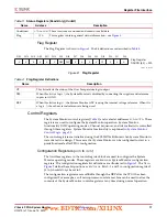
System Monitor Control Logic
ADC Channel Analog-Input Mode (
4Ch
and
4Dh
)
These registers are used to configure an ADC channel as either unipolar or bipolar in the
automatic sequence (see
). The registers have the same bit
assignments as the Channel Sequence and Channel Averaging registers. However, only
external analog-input channels, such as the dedicated-input channels V
P
, and V
N
, and the
Auxiliary Analog inputs V
AUXP
[15:0], and V
AUXN
[15:0]), can be configured in this way.
Setting a bit to logic 1 enables a bipolar input mode for the associated channel. Setting a bit
to logic 0 (default) enables a unipolar input mode. All internal sensors use a unipolar
transfer function.
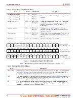
ADC Channel Acquisition Time (
4Eh
and
4Fh
)
The default acquisition time for an external channel in Continuous-Sampling mode is four
ADCCLK cycles. However, by setting the corresponding bits to logic 1 in registers
4Eh
and
4Fh
,
the associated channel can have its acquisition time extended to ten ADCCLK cycles. The bit
definitions (which bits correspond to which external channels) for these registers are the same
as the Channel Sequence registers described in
and
. For example, to extend the
acquisition time for channel V
AUXP
[1]/V
AUXN
[1], bit 1 in register
4Fh
is set to a logic 1.
Maximum and Minimum Status Registers
System Monitor also tracks the minimum and maximum values recorded for the internal
sensors since the last power-up or since the
last reset
of the System Monitor control logic.
The maximum and minimum values recorded are stored in the DRP Status registers
starting at address
20h
(see
). On power-up or after reset, all the
minimum registers are set to
FFFFh
and the maximum registers are set to
0000h
. Each
new measurement generated for an on-chip sensor is compared to the contents of its
maximum and minimum registers. If the measured value is greater than the contents of its
maximum registers, then the measured value is written to the maximum register. Similarly,
for the minimum register, if the measured value is less than the contents of its minimum
register, then the measured value is written to the minimum register. This check is carried
out every time a measurement result is written to the status registers.
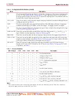
Automatic Alarms
System Monitor also generates an alarm signal on the logic outputs ALM[2:0] when an
internal-sensor measurement (Temperature, V
CCINT
, or V
CCAUX
) exceeds some user-
defined thresholds. Only the values written to the status registers are used to generate
alarms. If averaging has been enabled for a sensor channel, then the averaged value is
compared to the Alarm Threshold register contents. The alarm outputs are disabled by
writing a
1
to bits ALM2, ALM1, and ALM0 in Configuration register 1. The alarm
thresholds are stored in Control registers
50h
to
57h
(see
defines the alarm thresholds that are associated with specific Control registers.
The limits written to the threshold registers are MSB justified. Limits are derived from the
temperature and power-supply sensor transfer functions (see
and
).
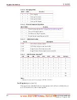
14
30
Enable averaging—VAUXP[14],VAUXN[14]—Auxiliary channel 15
15
31
Enable averaging—VAUXP[15],VAUXN[15]—Auxiliary channel 16
Table 16:
Sequencer ADC Channel Averaging, Control Register
4Bh
(Cont’d)
Bit
ADC Channel
Description
www.BDTIC.com/XILINX


