Virtex-6 FPGA System Monitor
53
UG370 (v1.1) June 14, 2010
Application Guidelines
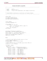
Example Instantiation using Verilog
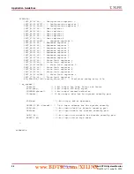
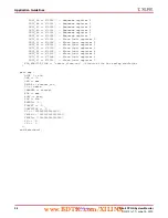
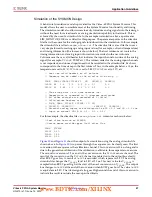
Below is an example of how this design is instantiated. This design can be instantiated in
any Virtex-6 device as a stand-alone design. Only an external clock is required to access the
data on the DO bus.
Note:
If the DCLK is not present or disconnected, SYSMON switches over to an internal clock
oscillator and continues to monitor V
CCAUX
. In this situation, data is not updated on the DO bus
because a DCLK is needed to access the DRP. The ALARM and BUSY signal remains active
however. The result in status register 2 (V
CCAUX
) can be accessed via the JTAG TAP (refer to
).
////////////////////////////////////////////////////////////////////////
//
// Author: Xilinx
// Date: July 11th 2007 $
// Design: Virtex-6 FPGA System Monitor Verilog example instantiation
//
// System Monitor instantiation by hand using the Language Template
//
////////////////////////////////////////////////////////////////////////
`timescale 1ns / 1 ps
module v5_sysmon
(
// Inputs
clk,
// Outputs
Vccaux,
busy,
alarm
);
//Inputs
input clk;
//Output
output [9:0] Vccaux;
output busy;
output alarm;
wire [15:0] dobus;
wire [4:0] channel;
wire [2:0] alm;
wire eos;
// bring out 10-bit (MSBs) version of DO bus
assign Vccaux = dobus[15:6];
assign alarm = alm[2];
// SYSMON: System Monitor
// Virtex-6
// Xilinx HDL Language Template, version 9.2.1i
www.BDTIC.com/XILINX


