26
Virtex-6 FPGA System Monitor
UG370 (v1.1) June 14, 2010
System Monitor Control Logic
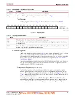
contents are not reset at this time. Restarting the sequencer by writing to bits SEQ1 and
SEQ0 resets all channel averaging (see
ADC Channel Selection (
48h
and
49h
)
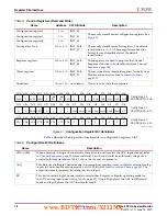
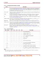
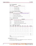
The ADC channel selection registers enable and disable a channel in the automatic
monitoring sequence. The bit definitions for these registers are described in
. The two 16-bit registers are used to enable or disable the associated channels. A
logic 1 enables a particular channel in the sequence. The sequence order is fixed starting
from the LSB (bit 0) of register
48h
and ending with the MSB (bit 15) of register
49h
.
Table 13:
Sequencer ADC Channel Selection, Control Register
48h
Sequence
Number
Bit
ADC
Channel
Description
1
0
8
System Monitor calibration
(1)
1
9
Invalid channel selection
2
10
3
11
4
12
5
13
6
14
7
15
2
8
0
On
-
Chip temperature
3
9
1
Average On
-
Chip V
CCINT
4
10
2
Average On
-
Chip V
CCAUX
5
11
3
V
P
,
V
N
—Dedicated analog inputs
6
12
4
V
REFP
(1.25V)
7
13
5
V
REFN
(0V)
14
6
Invalid channel selection
15
7
Notes:
1. See the
section for further details on how calibration is done
in an averaged sequence.
Table 14:
Sequencer ADC Channel Selection, Control Register
49h
Sequence
Number
Bit
ADC
Channel
Description
8
0
16
VAUXP[0],VAUXN[0]—Auxiliary channel 1
9
1
17
VAUXP[1],VAUXN[1]—Auxiliary channel 2
10
2
18
VAUXP[2],VAUXN[2]—Auxiliary channel 3
11
3
19
VAUXP[3],VAUXN[3]—Auxiliary channel 4
www.BDTIC.com/XILINX


