KCU1250 User Guide
22
UG1057 (v1.0) December 19, 2014
Chapter 1:
KCU1250 Board Features and Operation
System Controller GPIO Pushbuttons
SW5, SW6, SW10, SW11, SW12 (callout 36,
) are active-High pushbuttons
connected to GPIO pins on the system controller. See
for more details.
USB to Dual-UART Bridge
The KCU1250 board uses a single-chip USB to dual-UART bridge (U32, Silicon Laboratories
CP2105) for simultaneous serial communication between a host terminal and the UltraScale
FPGA, and between a host terminal and the Zynq-7000 AP SoC system controller. The
onboard micro-B receptacle USB connector J1 (callout 22,
) is connected to the
dual-UART bridge.
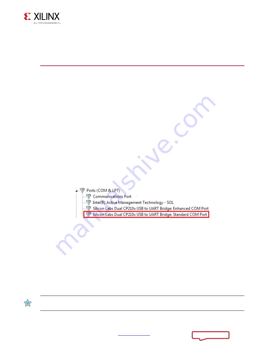
The FPGA connects through a serial communication terminal connection (115200-8-N-1)
using the standard communication port of the Silicon Labs USB to dual-UART bridge using
four signal pins:
• Transmit (TX)
• Receive (RX)
• Request to send (RTS)
• Clear to send (CTS)
The dual-UART interface connections are split between two components:
• UART1 SCI (standard) interface is connected to the XCKU040 FPGA
• UART2 ECI (enhanced) interface is connected to the XC7Z010 system controller
Silicon Labs provides royalty-free virtual COM port (VCP) drivers for the host computer.
These drivers permit the CP2105GM dual USB-to-UART bridge to appear as a pair of COM
ports to communications application software (for example, TeraTerm or HyperTerm) that
runs on the host computer.
IMPORTANT:
The VCP device drivers must be installed on the host PC prior to establishing
communications with the KCU1250 board.
X-Ref Target - Figure 1-10
Figure 1-10:
Silicon Labs USB to UART Bridge Standard COM Port
8*BB


