


Operation—Operating the Machine
Continued on next page
OUT4001,0000867 -19-26JUL21-1/2
Unlocking the Hydraulic Coupler From the
Attachment—If Equipped
CAUTION: Prevent possible injury or death from
unexpected hydraulic coupler movement. Make
sure hydraulic coupler is attached correctly
to attachment. The supplemental lock can be
engaged with the attachment in an incorrect
lock position. A visual check is required each
time the lock operation is performed.
CAUTION: Avoid personal injury. Prevent
injury from hydraulic coupler movement. Keep
bystanders clear of machine.
IMPORTANT: Prevent possible hydraulic coupler
damage from incorrect installation. Attaching
the bucket in a reverse orientation on the
hydraulic coupler is not recommended.
When installed in the reverse orientation,
the bucket or the lift hook interferes with
the arm of the excavator when the bucket is
in full curl position by extending the bucket
cylinder. This is an inherent part of the
design of the original equipment.
Since the hydraulic coupler interacts with
the arm at full curl position to unlock the
supplemental lock, the hydraulic coupler will
NOT operate properly when the bucket is
attached in reverse orientation.
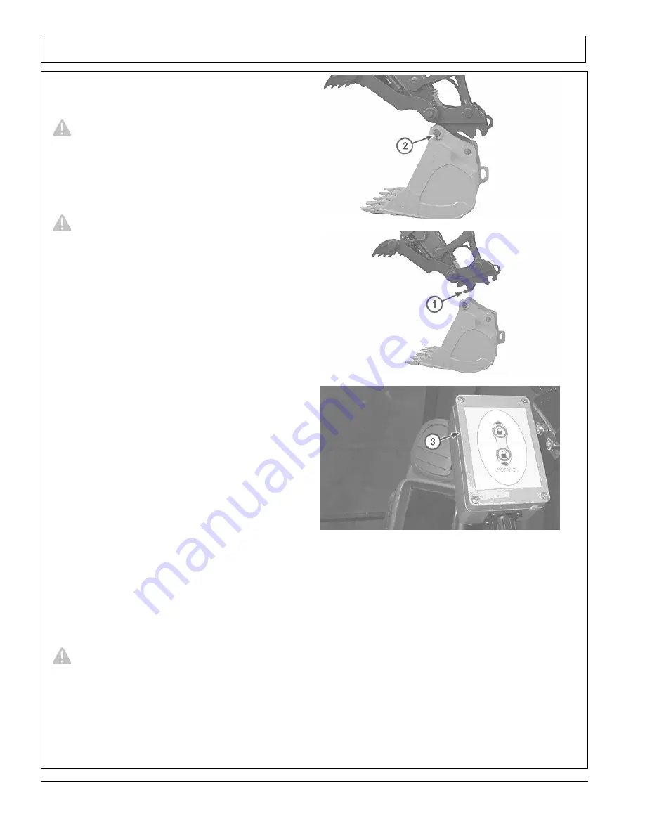
1. Keep attachment close to ground.
NOTE: The hydraulic coupler must be held over relief in
order to unlock the hydraulic coupler cylinder.
2. Rotate hydraulic coupler to full curl position to release
supplemental lock.
NOTE: The safety buzzer located on the hydraulic coupler
control box (3) will sound to alert personnel the
lock/unlock function has been activated.
3. Press UNLOCK button on hydraulic coupler control
box (3). Hold in full curl position for 5 seconds.
4. Slowly uncurl hydraulic coupler. Front hook (1) will
release from pin (2).
Reset Lock Controller
CAUTION: Avoid personal injury. Prevent
injury from hydraulic coupler movement. Keep
bystanders clear of machine.
The safety buzzer will sound if an error occurs with the
hydraulic coupler control box circuit.
1. Lower attachment to ground.
2. Turn key switch to OFF position.
TX1017662A
—UN—17JAN07
Hydraulic Coupler Pin
TX1017664A
—UN—17JAN07
Front Hook on Hydraulic Coupler
TX1
171396A
—UN—09SEP14
Hydraulic Coupler Control Box
1— Front Hook
2— Pin
3— Hydraulic Coupler Control
Box
3. Press and hold LOCK and UNLOCK buttons on
hydraulic coupler control box.
4. Turn key switch to ON position.
5. Continue to press and hold LOCK and UNLOCK
buttons for 20 seconds.
6. Safety buzzer and hydraulic coupler control box lights
will cycle on and off.
7. After safety buzzer stops, release LOCK and UNLOCK
buttons. Resume normal operation. If safety buzzer
will not turn off, contact an authorized John Deere
dealer.
2-3-15
092221
PN=116
Содержание 380GLC
Страница 6: ...Introduction Continued on next page TX JDEULA 19 11JUL16 2 3 TX1219046 UN 11JUL16 092221 PN 6...
Страница 7: ...Introduction TX JDEULA 19 11JUL16 3 3 TX1219047 UN 14JUL16 092221 PN 7...
Страница 9: ...Introduction DX EMISSIONS EPA 19 12DEC12 2 2 TS1721 UN 15JUL13 092221 PN 9...
Страница 13: ...Introduction Continued on next page DX EMISSIONS CARB 19 26AUG20 4 8 RG29281 UN 27FEB17 092221 PN 13...
Страница 16: ...Introduction Continued on next page DX EMISSIONS CARB 19 26AUG20 7 8 RG32758 UN 19AUG20 092221 PN 16...
Страница 17: ...Introduction DX EMISSIONS CARB 19 26AUG20 8 8 RG32759 UN 19AUG20 092221 PN 17...
Страница 24: ...Introduction 092221 PN 24...
Страница 287: ...Index Index 11 092221 PN 11...
Страница 288: ...Index Index 12 092221 PN 12...