12 english
securely on the table.
m
Proper Use
The machine meets the currently valid EU machine directive.
• The manufacturer’s safety, operation and maintenance
instructions as well as the technical data given in the
calibrations and dimensions must be adhered to.
• Relevant accident prevention regulations and other gen
-
erally recognized safety and technical rules must also
be adhered to.
• The machine may only be used, maintained or repaired
by trained persons who are familiar with the machine
and have been informed about the dangers. Unauthor-
ized modifications of the machine exclude a liability
of the manufacturer for damages resulting from the
modifications.
• The machine is intended for use only with original spare
parts and original tools from the producer.
• Any other use is considered to be not intended. The
manufacturer excludes any liability for resulting dam-
ages, the risk is exclusively borne by the user.
m
Remaining hazards
The machine has been built using modern technology and
in accordance with recognized safety rules.
Some hazards, however, may still remain.
• There is the danger of injuries to fingers and hands by
the rotating grinding tool when there is improper guid-
ance or application of the work piece to be grinded.
• There is a danger of injuries by catapulted work pieces
when guided or fixed improperly.
• The use of incorrect or damaged mains cables can lead
to electrical injuries.
• Although having regarded all considerable rules there
may still remain not obvious remaining hazrds.
• Minimize remaining hazards by following the instruc
-
tions in ”Safety Rules”, ”Use only as authorized” and
in the entire operating manual.
Commissioning
ATTENTION!!
Always disconnect the power supply before be-
ginning any maintenance or setup work on the machine.
Mounting belt/disc sander to work bench
If your belt/disc sander is to be used in a permanent loca-
tion, it is recommended you secure it to a workbench or
other stable surface. When mounting the belt/disc sander
to a workbench, holes should be drilled through the sup-
porting surface of the workbench.
• Mark holes on workbench where belt/disc sander is to
be mounted using holes in the base as a template for
hole pattern.
• Drill holes through workbench.
• Place belt/disc sander on workbench aligning holes in
the base with holes drilled in the workbench.
• Insert bolts (not included) and tighten securely with
lock washers and hex nuts (not included).
Note: All bolts should be inserted from the top. Install the
lock washers and hex nuts from the underside of the work-
bench.
Clamping belt/disc sander to work bench
If your belt/disc sander is to be used as a portable tool, it
is recommended you fasten it permanently to a mount-
ing board that can easily be clamped to a workbench
or other stable surface. The mounting board should be
of sufficient size to avoid tipping while belt/disc sander
is in use. Any good grade plywood or chipboard with a
3/4 in. (19 mm) thickness is recommended.
• Mark holes on board where belt/disc sander is to be
mounted using holes in the base as a template for hole
pattern.
• Follow last three steps in section Mounting Belt/Disc
Sander to Workbench.
If lag bolts are used, make sure they are long enough to
go through holes in belt/disc sander base and material the
belt/ disc sander is being mounted to. If machine bolts are
used, make sure bolts are long enough to go through holes
in belt/disc sander, the material being mounted to, and
the lock washers and hex nuts.
Connection to vacuum suction.
The use of an extraction system is recommended.
For this the vacuum connector (10) and two different
adaptors (11) are provided.
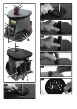
Tool changes, Fig. 2–7
ATTENTION!!
Turn off the machine and disconnect the main
plug.
When changing tools make sure to have all parts cleaned.
Prepare the appropriate tool and mount it as follows:
1. Attach the lower spindle disc (16) to the spindle (4)
(fig.2).
2. Insert the table inlays (5) into the table (fig. 3).
3. Attach the lower spindle disc (6) to the spindle (4)
(fig.2).
4. Slide the abrasive sleeve (7) onto the rubber sleeve (6)
(fig. 5).
5. Apply the disc (13) (use the correct measurements) (fig.
6).
6. Put on the hex-nut and tighten it with the hook wrench
(14). (fig. 7)
Be sure always to mount the correct parts when changing
the abrasive sleeves. The table inlays have to be bigger
than the abrasive sleeves. (fig. 8)
Note!
The 13mm abrasive sleeve is put directly onto the
spindle (4).
Table:
Abrasive sleeve
inside D
Table inlay inside
D
Spindle disc size
13 mm
18 mm
small 16 mm
19 mm
25 mm
medium 20 mm
26 mm
31 mm
medium 20 mm
38 mm
44 mm
large 35 mm
51 mm
57 mm
large 35 mm
76 mm
82 mm
large 35 mm
Initial operation
After completing all assembly and setup work, turn on the
machine and while it idles, check that the spindle can
move faultlessly. In the case of disturbances, turn the ma-
chine off immediately and rectify the cause.
Once the machine has reached its maximum revolution
speed you ay start the grinding work.
Move the work piece slowly in the direction contrary to the
running direction of the grinding roll.
Do not overload the machine by too much pressure against
the grinding roll.
Содержание Os 58
Страница 4: ...Fig 1 1 2 3 4 5 5 15 13 8 9 4 6 7 10 12 14 Fig 2 Fig 3 Fig 4 Fig 5 Fig 6 Fig 7 Fig 8...
Страница 19: ...fran ais 19...
Страница 25: ......
Страница 26: ......
Страница 27: ......

