


36
ACW-DINDxxx_UG_EN_V1.8
A
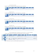
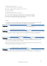
pply a state to outputs’ group
(Command 0x11)
It is possible to assign the state of a group of outputs to a value without affecting the state of the other
outputs, it will be necessary to send the following command:
Byte 0
Byte 1
Byte 2
Byte 3
Byte 4
0xc1
3
0x11
Masque/Groupe
États des sorties
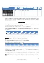
Each output is represented by a bit in byte 4 and byte 5. Byte 0 of these bytes corresponds to output 1,
..., bit 7 corresponds to output 8.
Byte 5 has the same role as byte 3 of the 0x10 command, the only difference being that the outputs
specified in byte 4 will be driven by the ACW.
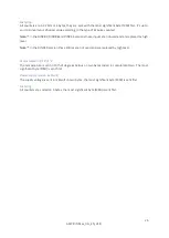
Following this command, the ACW will return a response in the following format:
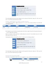
Description and value
Byte 0
Answer to command frames
: 0x07
Byte 1
Command ‘
Apply a state to outputs
’: 0x1
1
Byte 2
Outputs states after command execution
Byte 3
States of outputs to command, but which does not exist.
The constituted frame has the same behavior as with the 0x10 command. The difference is that the
errors are based on byte 4 of the (control) frame 0x11. On DIND44 outputs 5 to 8 can not be controlled,
bits 4 to 7 of byte 4 of frame 0x11 must therefore be 0 to avoid errors. In the case of an error, none of
the outputs will be controlled.
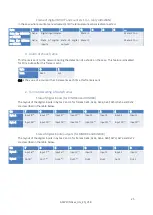
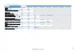
Generate a positive pulse to an outputs group (Command 0x12)
It is possible to generate a positive impulse (0-> 1-> 0), for that, it will be necessary to send the following
command:
Byte 0
Byte 1
Byte 2
Byte 3
Byte 4
0xc1
3
0x12
Mask/Group
Pulse time
Each output to be controlled is represented by a bit in byte 4. Byte 0 of byte 4 corresponds to output 1,
..., bit 7 corresponds to output 8.
Byte 5 corresponds to the pulse time in milliseconds with a ratio of 4. The minimum value is therefore
4 ms and the maximum value is 1020 ms.
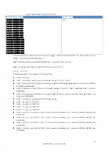
Following this command, the ACW will return a response in the following format:


