25
ACW-DINDxxx_UG_EN_V1.8
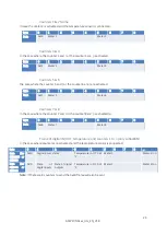
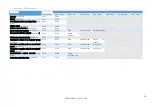
Frame of digital IN/OUT and counters 1 to n (only LoRaWAN)
In the case where counters are activated, and the temperature sensor is disconnected.
Byte
0
1
2
3
4
5
6
...
Data (for DIND160
or DIND80
0x5e
Digital inputs states
Meter 1
Meter 2 to n
Data (for DIND44
or DIND88
0x7e
State of digital
inputs
State of digital
outputs
Meter 1
Meter 2 to n
d.
Alarm of shock frame
This frame is sent to the network during the detection of a shock on the case. This feature is disabled
for 10 minutes after this frame is sent.
Byte
0
1
Data
0x43
cnt
Cnt
is the value of a counter that increments each time this frame is sent.
e.
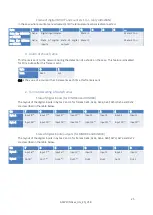
Format/decoding of data/frames
State of digital inputs (for DIND160 and DIND80)
The layout of the digital inputs in bytes 2 and 3 for frames 0x41, 0x42, 0x4e, 0x4f, 0x5d, 0x5e and 0x52
are described in the table below.
Bit
7
6
5
4
3
2
1
0
Byte 2
Input 8
(2)
Input 7
(2)
Input 6
(2)
Input 5
(2)
Input 4
Input 3
Input 2
Input 1
Byte 3
Input 16
(1)
Input 15
(1)
Input 14
(1)
Input 13
(1)
Input 12
(1)
Input 11
(1)
Input 10
(1)
Input 9
(1)
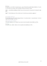
State of digital inputs/outputs (for DIND88 and DIND44)
The layout of the digital inputs in bytes 2 and 3 for frames 0x61, 0x62, 0x6e, 0x6f, 0x7d, 0x7e and 0x72
are described in the table below.
Bit
7
6
5
4
3
2
1
0
Byte 2
Input 8
(2)
Input 7
(2)
Input 6
(2)
Input 5
(2)
Input 4
Input 3
Input 2
Input 1
Byte 3
Out 8
(3)
Out 7
(3)
Out 6
(3)
Out 5
(3)
Out 4
Out 3
Out 2
Out 1


