45/47
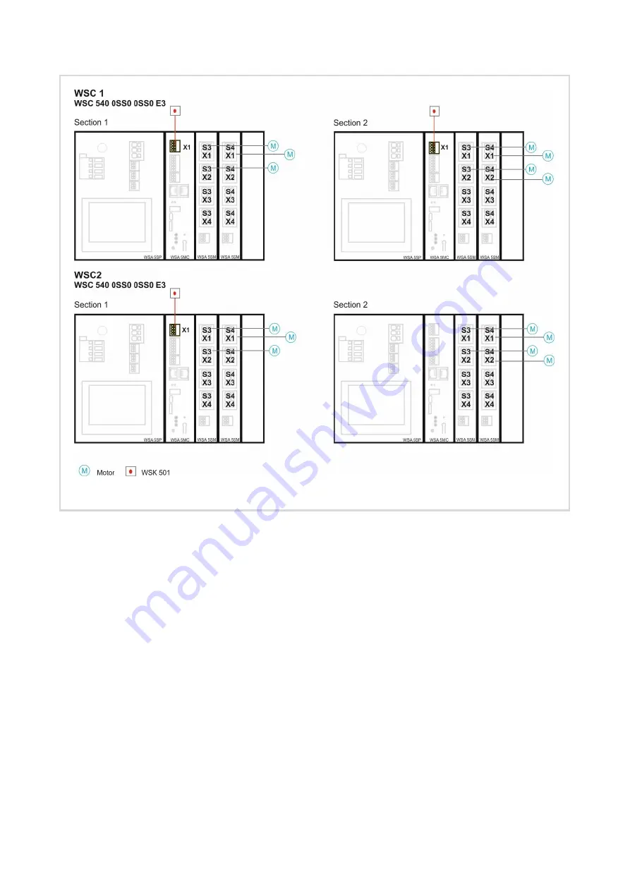
Figure 12 overview of the smoke panels and how the different components are connected to it.
5.3 Configuration
A detailed description of how to use the touchscreen, to configure the different elements (motor lines, motor
groups, break glass units, comfort keypads, BMS, rain sensors, weather station etc.), can be found in the
previous examples.
In this example, we will only go through what needs to be done in order to meet the system requirements
and explain the reasons for the selected configuration.
5.3.1 Configuration of the CAN bus
The CAN ID of a section on a CAN bus, must be unique. Configure, therefor the CAN IDs as follows:
WSC1.Section1 = 1
WSC1.Section2 = 2
WSC2.Section1 = 3
WSC2.Section2 = 4
5.3.2 Basic configuration
Associate motor lines to motor groups, motor groups to smoke zones and break glass units to smoke zones
as shown in the hardware illustration above.


