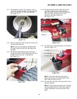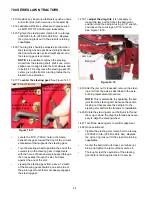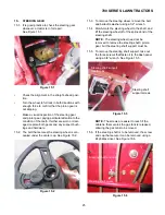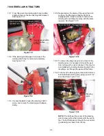
700 SERIES LAWN TRACTORS
37
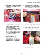
•
Interpretation
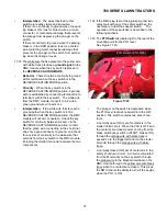
: The wires that lead to this
switch are readily visible and traceable.
If there is no continuity to ground when the park-
ing brake is ON, look for broken wires, a loose
connector, or mechanical damage that prevents
the linkage from depressing the plunger on the
switch.
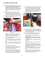
If there is continuity to ground when the parking
brake is in the RUN position, look for a chafed
wire contacting metal or physical damage that
prevents the plunger on the switch from extend-
ing when the linkage moves.
17.23.The white wire that is adjacent to the yellow wire
with white trace provides a
ground signal
to the
RMC module when the key switch is placed in
the
REVERSE CAUTION MODE.
•
Behavior
: There should be continuity to ground
at this terminal when the key switch is in the
REVERSE CAUTION MODE position.
•
Circuitry
: When the key switch is in the
REVERSE CAUTION MODE position, a ground
path is established by connecting terminal A2 to
terminal L within the key switch. The white wire
from the RMC module connects to A2, and a
green ground wire connects to L.
•
Interpretation
: If the white wire fails to reach a
ground path when the key switch is in the
REVERSE CAUTION MODE position, the RMC
module will not arm or operate. Check the key
switch for continuity between A2 and L in the
REVERSE CAUTION MODE position, confirm
that the green wire connecting to the L terminal
does have good continuity to ground, and check
for any loss of continuity in the white wire that
extends from the key switch to the RMC module,
including the molded connector between the two
components.
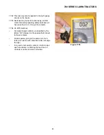
17.24.If the RMC plug test or the pigtail plug test indi-
cates fault with any of the safety switches, the
next step is to test the suspect switch. The
operation of those switches is described in the
following sections.
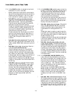
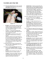
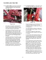
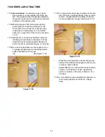
17.25.The
PTO Switch
is located just to the rear of the
mounting point for the PTO lever.
See Figure 17.25.
•
The plunger on the switch is depressed when
the PTO lever is drawn rearward into the OFF
position. The switch contains two sets of con-
tacts.
•
A normally open (NO) set of contacts is in the
starter inhibit circuit. When the PTO is OFF, and
the contacts are closed, power coming from the
brake switch (key switch in START, brakes ON)
through the orange wire with black trace is
passed on to the trigger terminal on the starter
solenoid through the orange wire with white
trace.
•
A normally closed (NC) set of contacts is in the
safety shut-down circuit. A circuit is completed
from the M terminal on the key switch through
the yellow wire to the Magneto terminal on the
RMC module through the yellow wire with black
trace when the contacts are closed. This gives
the RMC module the ability to turn-off the engine
when the PTO is ON.
Figure 17.25
PTO Switch (PTO OFF)
Содержание 700 Series
Страница 2: ......
Страница 4: ......
Страница 50: ...700 SERIES LAWN TRACTORS 46 ...
Страница 52: ...700 SERIES LAWN TRACTORS 48 ...

