700 SERIES LAWN TRACTORS
8
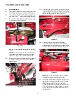
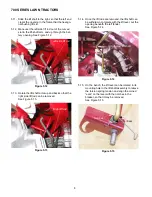
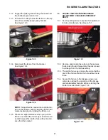
5.11. Slide the lift shaft to the right, so that the left end
clears the opening in the frame that the hexago-
nal bushing fits in.
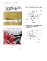
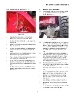
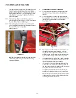
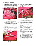
5.12. Maneuver the left side lift rod out of the curved
slot in the lift-shaft arm, and up through the bat-
tery opening. See Figure 5.12.
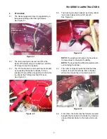
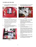
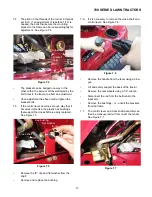
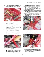
5.13. Rotate the lift shaft arms up and back so that the
right side lift rod can be removed.
See Figure 5.13.
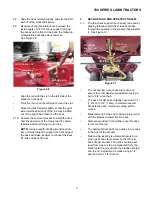
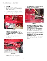
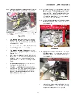
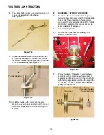
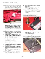
5.14. Once the lift rods are removed, the lift shaft can
be withdrawn, complete with the lift lever, out the
opening beneath the left fender.
See Figure 5.14.
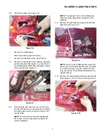
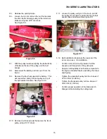
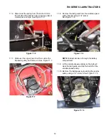
5.15. On the bench, the lift lever can be rotated in its
mounting hole in the lift shaft assembly to relieve
the torsion spring tension and align the coined
“ears” on the lever with the notches in the
bracket, so that it may be removed.
See Figure 5.15.
Figure 5.12
Left side lift rod
Figure 5.13
Right lift rod
Figure 5.14
Withdraw lift shaft
Figure 5.15
Ears
Notches
Содержание 700 Series
Страница 2: ......
Страница 4: ......
Страница 50: ...700 SERIES LAWN TRACTORS 46 ...
Страница 52: ...700 SERIES LAWN TRACTORS 48 ...


