700 SERIES LAWN TRACTORS
20
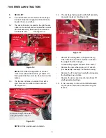
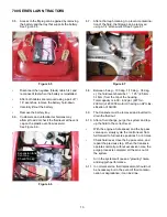
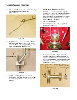
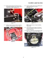
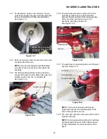
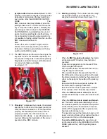
11.11. Remove the crankshaft pulley using a 5/8”
wrench. See Figure 11.11.
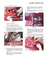
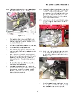
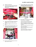
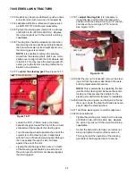
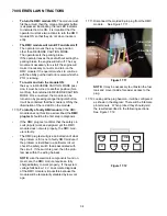
11.12. Pulley Hardware: The pulley is secured by a
bolt, lock washer, and a heavy flat washer. A
spacer is positioned above it on the crankshaft,
with the top edge radius matching the step in the
crankshaft. The key is integral with the stack
pulley. See Figure 11.12.
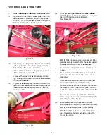
11.13. Belt installation is basically the reversal of the
removal process. On installation:
•
Confirm correct belt routing inside of all the
keepers and through all of the guide pins.
•
Apply a small quantity of anti-seize compound to
the engine crankshaft before installing the crank-
shaft pulley.
•
Tighten the crankshaft pulley bolt to a torque of
37.5-50 ft-lb. (51-68 Nm).
•
Tighten the transaxle pulley nut to a torque of
10-15 ft.-lb. (13.6-20.3 Nm).
•
Confirm proper operation of the brake/clutch
linkage before installing the cutting deck.
•
Adjust the speed control linkage if necessary.
•
Confirm proper operation of tractor safety fea-
tures before returning the tractor to service.
12.
SPEED CONTROL LINKAGE ADJUSTMENT:
VARIABLE SPEED BELT DRIVE
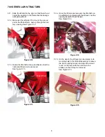
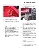
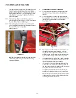
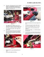
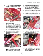
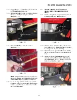
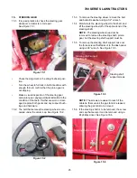
12.1. Because of the change of tensions with new
belts it is always advisable to check all drive
adjustments after changing the drive belts.
See Figure 12.1.
Figure 11.11
Belt keeper
screws and
spacers
Belt keeper
tabs
Figure 11.12
Bolt Lock washer Stack pulley Spacer
Flat washer shoulder
(rounded
to engine)
Figure 12.1
Control Rod
Variable Speed
Содержание 700 Series
Страница 2: ......
Страница 4: ......
Страница 50: ...700 SERIES LAWN TRACTORS 46 ...
Страница 52: ...700 SERIES LAWN TRACTORS 48 ...

